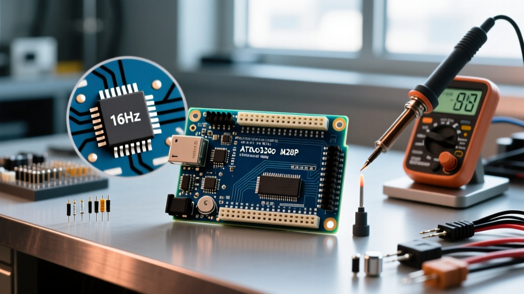

The Heartbeat of the Uno: Understanding the 16MHz Baseline
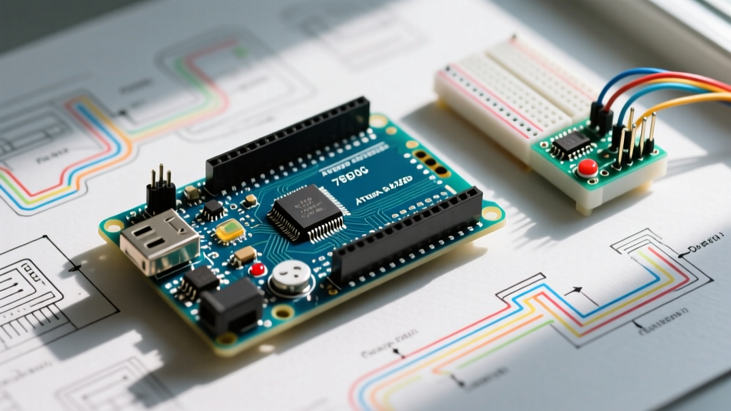
When engineers and hobbyists discuss the Arduino Uno clock speed, they are almost exclusively referring to the 16 MHz quartz crystal oscillator that dictates the execution rhythm of the ATmega328P microcontroller. In the AVR architecture, most instructions execute in a single clock cycle. Therefore, a 16 MHz clock speed translates directly to a theoretical maximum of 16 Million Instructions Per Second (MIPS). Each clock cycle lasts exactly 62.5 nanoseconds.
However, as we navigate the hardware landscape of 2026, the definition of an "Arduino Uno" has bifurcated. The classic Uno R3 (and its modern SMD revisions) relies on the 8-bit ATmega328P at 16 MHz, while the newer Uno R4 Minima and WiFi models utilize a 32-bit Renesas RA4M1 Cortex-M4F running at a vastly superior 48 MHz. This deep dive focuses primarily on the legacy 16 MHz architecture that still powers millions of active deployments, while contrasting it with modern alternatives where clock speed fundamentally alters peripheral behavior.
How Clock Speed Governs Peripheral Limits
The Arduino Uno clock speed is not just about raw code execution; it is the master reference for every hardware peripheral on the board. If you alter the clock speed, or if your board's oscillator drifts, your peripherals will fail in predictable, mathematically calculable ways.
Serial Communication and Baud Rate Math
UART serial communication relies on dividing the system clock to generate the timing for individual bits. The ATmega328P uses the USART Baud Rate Register (UBRR) to calculate this timing. The formula is:
UBRR = (f_osc / (16 * BAUD)) - 1
If you attempt to use the standard 115,200 baud rate on a 16 MHz Uno, the math yields a UBRR of 7.68. Since the hardware register only accepts integers, it rounds to 8. This results in an actual baud rate of 111,111 bps, introducing a -3.5% timing error. While most modern USB-to-Serial adapters (like the ATmega16U2 on genuine Unos or the CH340C on clones) can tolerate a ±4% drift, pushing to 250,000 baud at 16 MHz results in a 0% error, making it a mathematically "perfect" baud rate for this specific clock speed.
Timers, PWM, and the millis() Function
The Uno features three hardware timers that divide the 16 MHz clock using prescalers (1, 8, 64, 256, 1024). Understanding this division is critical for precision timing:
- Timer0 (8-bit): Configured with a prescaler of 64 by the Arduino core. 16,000,000 / 64 = 250,000 Hz. This 8-bit timer overflows every 256 ticks, triggering an interrupt every 1.024 milliseconds. This is the hidden engine behind the
millis()anddelay()functions. - Timer1 (16-bit): Typically used by the Servo library. Its 16-bit resolution allows for high-precision PWM generation without overflowing as rapidly as Timer0.
- Timer2 (8-bit): Often used for the
tone()function and asynchronous RTC operations when paired with an external 32.768 kHz watch crystal.
Hardware Comparison: Uno R3 (16MHz) vs. Uno R4 (48MHz)
To contextualize the limitations of the 16 MHz ATmega328P, we must compare it to the current-generation Uno R4 architecture. The leap in clock speed fundamentally changes what is possible regarding floating-point math and high-speed data acquisition.
| Feature | Uno R3 (ATmega328P) | Uno R4 (Renesas RA4M1) |
|---|---|---|
| Clock Speed | 16 MHz | 48 MHz |
| Architecture | 8-bit AVR | 32-bit ARM Cortex-M4F |
| Floating Point Unit (FPU) | None (Software emulation) | Hardware Single-Precision FPU |
| Max PWM Frequency | ~31.25 kHz (Phase Correct) | Up to 48 MHz (via specialized timers) |
| Typical Retail Price (2026) | $27.00 (Genuine) | $45.00 (WiFi Model) |
Source: Arduino Official Hardware Documentation
The Clone Problem: Ceramic Resonators vs. Quartz Crystals
When analyzing Arduino Uno clock speed in real-world deployments, hardware authenticity matters. Genuine Arduino Unos use a high-precision quartz crystal oscillator (typically rated for ±30 ppm stability). In contrast, the vast majority of sub-$12 clone boards manufactured in Shenzhen utilize ceramic resonators to save roughly $0.15 per unit on the BOM.
Ceramic resonators have a typical tolerance of ±0.5%. While this sounds negligible, a 0.5% drift at 16 MHz equals an 80,000 Hz variance. If your project operates in an unheated garage or an outdoor enclosure, temperature fluctuations will exacerbate this drift. This is a primary reason why clone boards frequently experience corrupted data transfers when using high-speed I2C or tight-tolerance UART protocols, whereas genuine boards maintain synchronization.
Overclocking the ATmega328P to 20MHz
Can you push the Arduino Uno clock speed beyond its 16 MHz factory limit? Yes. According to the Microchip ATmega328P Datasheet, the maximum rated clock frequency for the chip operating at 5.0V is exactly 20 MHz. Overclocking to 20 MHz yields a 25% performance bump, allowing for faster SPI polling and higher software-based PWM resolutions.
Step-by-Step Overclocking Procedure
Warning: This requires SMD or through-hole soldering and will permanently alter your board's timing profiles.
- Hardware Swap: Desolder the factory 16 MHz crystal (or ceramic resonator). Solder in a 20.000 MHz HC49/S quartz crystal (e.g., Abracon ABLS-20.000MHZ-B2-T, costing roughly $0.40). Ensure you use matching 22pF load capacitors if your new crystal requires them.
- Software Core Installation: The default Arduino IDE core hardcodes the 16 MHz assumption. You must install the MiniCore AVR hardware package via the Boards Manager. MiniCore provides native, highly optimized support for 20 MHz external clocks.
- Bootloader Burning: Connect an ISP programmer (like a USBasp or another Arduino running the ArduinoISP sketch) to the ICSP header. Select the ATmega328P target, set the clock to 20 MHz external, and click "Burn Bootloader." This updates the fuses and replaces the baud-rate timing tables.
- Recalibrating Delays: Once flashed, standard
delay(1000)functions will execute perfectly, as MiniCore recompiles the timing macros based on the new F_CPU definition. However, any hardcoded register manipulations (like directUBRRorOCRwrites) in your existing code must be manually recalculated for 20 MHz.
What Breaks at 20MHz?
Overclocking is not without edge cases. The EEPROM write cycle time on the ATmega328P is strictly bounded by the internal RC oscillator and clock scaling. Running at the absolute silicon limit of 20 MHz can occasionally cause EEPROM write corruption if the supply voltage sags below 4.8V during a write cycle. Furthermore, if you are using the board's 5V linear regulator to power external sensors, the increased current draw of the MCU switching at 20 MHz may cause the onboard regulator to overheat in poorly ventilated enclosures.
Summary: Choosing the Right Clock Architecture
The 16 MHz Arduino Uno clock speed remains a masterclass in predictable, deterministic 8-bit computing. For 90% of DIY sensor nodes, relay controllers, and educational projects, the 16 MHz ATmega328P provides more than enough throughput. However, if your 2026 project demands hardware floating-point math, high-resolution DAC outputs, or zero-error high-baud-rate UART streaming, it is time to abandon the 16 MHz ceiling and migrate to the 48 MHz Uno R4 or an ESP32-S3 platform. Understanding the mathematical relationship between your oscillator, your prescalers, and your peripheral registers is what separates a casual coder from an embedded systems engineer.