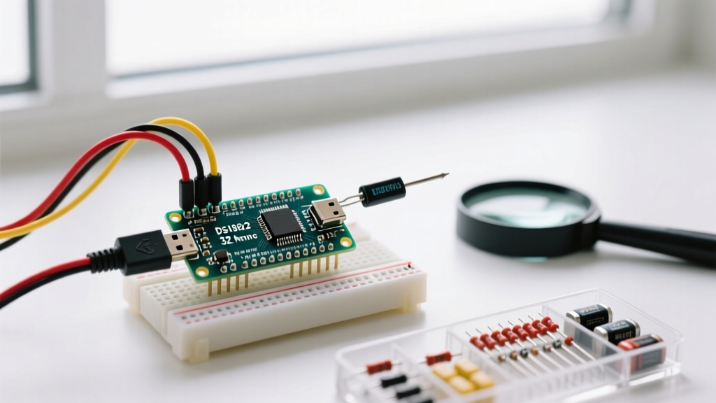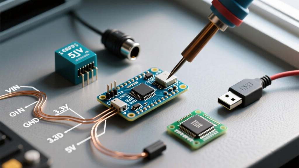

The Platform Migration Guide: Transitioning to the Arduino Nano
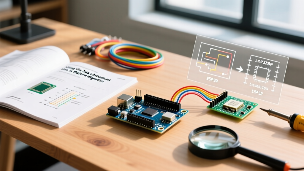
Migrating a project from a full-sized Arduino Uno or Mega to the compact Arduino Nano is a rite of passage for embedded systems engineers and DIY enthusiasts. You are moving from a prototyping phase to a space-constrained deployment. However, this physical downsizing introduces critical electrical engineering challenges—specifically regarding your Arduino Nano power source architecture. What worked flawlessly on an Uno's spacious PCB can cause thermal shutdowns, brownouts, or silicon damage on the Nano.
In 2026, the market is flooded with both official Arduino Nano boards and highly capable USB-C clones featuring the CH340G serial chip. Understanding the exact current limits, thermal dissipation profiles, and voltage regulator topologies of these boards is non-negotiable for a successful migration. This guide provides the exact specifications, failure modes, and architectural shifts required to power your Nano reliably.
Uno vs. Nano: Power Architecture Comparison
Before rewiring your project, you must understand how the Nano's power delivery network (PDN) differs from the Uno. The Uno utilizes a through-hole or large SMD linear regulator with a generous copper pour acting as a heatsink. The Nano compresses this into a tiny SOT-223 package with minimal thermal relief.
| Feature | Arduino Uno R3 / R4 | Classic Arduino Nano ( & 2026 Clones) |
|---|---|---|
| USB Interface | ATmega16U2 (Official) / CH340 (Clones) | FT232RL (Official) / CH340G (Clones) |
| USB Current Limit | 500mA (Resettable Polyfuse) | 500mA (Mini-B) / 1A+ (USB-C Clones) |
| Onboard 5V Regulator | NCP1117ST50T3G (SOT-223, large thermal pad) | AMS1117-5.0 (SOT-223, minimal copper pour) |
| Safe Vin Continuous Draw | ~300mA @ 9V Input | ~150mA @ 9V Input |
| Reverse Polarity Protection | Yes (Diode on DC Jack) | No (On Vin Pin) |
Evaluating Your Arduino Nano Power Source Options
When migrating your schematic, you have three primary paths to deliver power to the ATmega328P microcontroller and your peripheral sensors. Choosing the wrong path is the leading cause of migration failure.
1. USB Power (The Safest Baseline)
Powering via the USB port is the most stable method for bench testing and low-power deployments. The official Nano uses the Mini-B standard, while modern 2026 clones predominantly use USB-C. The USB 5V line is routed directly to the board's 5V rail, bypassing the onboard linear regulator entirely. According to the official Arduino Nano hardware guide, the USB port can safely supply up to 500mA. If you are using a modern USB-C clone, ensure your wall adapter or power bank supports the USB Battery Charging (BC 1.2) specification to prevent data-line negotiation timeouts.
2. The 5V Pin (Direct Injection)
If you are migrating to a custom PCB or perfboard and have a clean, regulated 5V supply, you can inject power directly into the '5V' pin. Warning: This bypasses all onboard protection. There is no reverse polarity protection, no overvoltage protection, and no polyfuse on this trace. If your external 5V supply spikes to 6V, you will instantly fry the ATmega328P. Only use this method if your external buck converter is of high quality and features over-voltage protection (OVP).
3. The Vin Pin (The Thermal Trap)
The 'Vin' (Voltage In) pin feeds directly into the onboard AMS1117-5.0 linear regulator. While the AMS1117 datasheet claims an 800mA output capability, that is only true if the IC is mounted on an infinite heatsink. On the Nano's tiny PCB, the thermal resistance from junction-to-ambient is roughly 50°C/W.
The Thermal Math: If you supply 12V to Vin and draw just 150mA for your sensors, the regulator drops 7V. Power dissipated = 7V × 0.15A = 1.05 Watts. Multiplying 1.05W by the 50°C/W thermal resistance yields a 52.5°C temperature rise above ambient. In a warm enclosure, the silicon junction will rapidly exceed 125°C, triggering the AMS1117's internal thermal shutdown and causing your Nano to endlessly reboot.
Step-by-Step Migration: Recalculating Your Current Budget
When moving from an Uno to a Nano, you must audit your peripheral current draw. The Uno's larger regulator could mask sloppy power budgeting; the Nano will not. Follow this workflow to recalculate your budget:
- Audit the Microcontroller: The ATmega328P draws roughly 15mA to 20mA at 16MHz and 5V.
- Audit the USB-Serial IC: If using an official Nano, the FT232RL consumes ~15mA. If using a 2026 clone with a CH340G, budget ~30mA.
- Audit Peripherals: A standard I2C OLED display (SSD1306) draws ~20mA. A single WS2812B RGB LED at full white draws 60mA. Just three WS2812B LEDs will max out the Nano's Vin regulator if powered from a 9V battery.
- Apply the 80% Rule: Never design a system that utilizes more than 80% of the regulator's safe thermal limit. For Nano Vin power, cap your total external draw at 120mA.
Common Migration Failure Modes & Troubleshooting
If your migrated project is unstable, check for these specific Nano-related failure modes:
- The 9V Battery Sag: Many beginners migrate their Uno's 9V alkaline battery setup to the Nano's Vin pin. A standard 9V alkaline battery has a high internal resistance. Under a 150mA load, the voltage sags below the AMS1117's dropout voltage (~6.2V), causing the 5V rail to collapse to 4V, leading to erratic sensor readings and brownouts.
- USB Polyfuse Tripping (Clones): Some cheaper Nano clones use undersized resettable polyfuses on the USB VBUS line. If you plug in a capacitive-heavy sensor shield, the inrush current will trip the fuse, leaving the board dead for 3-5 minutes until the fuse cools.
- Backfeeding via USB: If you power the Nano via the 5V pin and leave it plugged into a PC via USB, you are backfeeding your external 5V supply directly into the PC's USB port. This can damage your computer's motherboard. Always use a USB isolator or physically cut the 5V trace on the Nano's USB connector if dual-powering.
Expert Recommendations for 2026 Nano Deployments
To achieve true reliability when migrating to the Nano form factor, abandon the onboard linear regulator for any project drawing more than 100mA or requiring input voltages above 7V. Instead, adopt modern switching regulator topologies.
The External Buck Converter Solution
For projects running off 12V or 24V industrial supplies, integrate a micro-sized switching buck converter. The Pololu 5V, 500mA Step-Down Voltage Regulator D24V5F5 is an industry standard for this exact migration. Priced around $6.95, it operates at up to 90% efficiency. Unlike the Nano's linear AMS1117, the Pololu D24V5F5 will barely get warm when stepping 12V down to 5V at 300mA, completely eliminating thermal shutdown risks. Wire the output of this buck converter directly to the Nano's 5V pin.
The LiPo Migration Path
If you are migrating to a battery-powered, portable Nano device, drop the 9V alkaline approach entirely. The optimal 2026 architecture utilizes a single-cell 3.7V LiPo battery paired with a TP4056 charging module and a 5V boost converter (like the MT3608 or Adafruit PowerBoost). As detailed in SparkFun's comprehensive project powering guide, managing battery chemistry and boost efficiency is vastly superior to burning through alkaline cells via a linear regulator.
Final Migration Checklist
Before soldering your Nano into its final enclosure, verify the following:
- [ ] Total current draw on the 5V rail is calculated and verified with a multimeter.
- [ ] If using Vin, input voltage is kept between 7V and 9V maximum.
- [ ] High-current actuators (motors, relays, LED strips) are powered by an external supply, sharing a common ground with the Nano, not drawing through the Nano's 5V pin.
- [ ] USB data lines are isolated if the board is being powered by an external high-voltage source.
By respecting the physical limitations of the Nano's compact PCB and upgrading your power delivery topology, your migrated project will achieve the same rock-solid reliability as your full-sized prototypes, but in a fraction of the space.