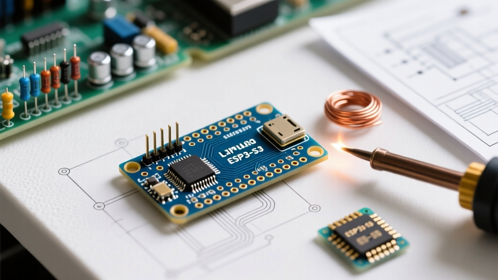

Introduction to the Nano ESP32 Architecture
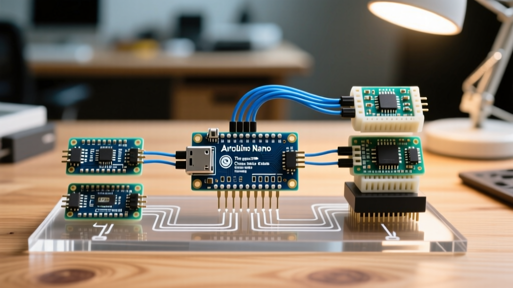
The Arduino Nano ESP32 represents a fundamental shift in the microcontroller landscape, merging the beloved physical footprint of the classic Arduino Nano with the high-performance, dual-core architecture of the ESP32-S3. Retailing between $21.00 and $24.50 depending on the distributor, this board is positioned for developers who need Wi-Fi and Bluetooth 5 capabilities without sacrificing the breadboard-friendly form factor of the original Nano.
However, transitioning from the classic ATmega328P-based Nano to this new iteration requires a complete mental remapping of the hardware. The Arduino Nano ESP32 pinout is not a 1:1 electrical clone of its predecessor. While the physical silkscreen labels (D2, A0, TX, RX) remain familiar, the underlying GPIO assignments, logic voltage levels, and peripheral routing are entirely different. This review dissects the exact pinout, highlights critical hardware differences, and compares the board against both the classic Nano and standard ESP32 development kits.
Under the Hood: The u-blox NORA-W106 Module
Unlike standard Espressif dev boards that expose raw ESP32-S3 chips, the Arduino Nano ESP32 utilizes the u-blox NORA-W106 system-in-package (SiP). This module integrates the ESP32-S3 dual-core Xtensa LX7 microcontroller (clocked at 240 MHz), 8 MB of Quad SPI flash, and a PCB antenna for 2.4 GHz wireless communication. This integration ensures superior RF shielding and FCC/CE compliance out of the box, but it also dictates specific internal GPIO routing that developers must respect when designing custom PCBs or shields.
The Complete Arduino Nano ESP32 Pinout Mapping
Understanding the Arduino Nano ESP32 pinout requires distinguishing between the physical silkscreen labels on the PCB and the actual ESP32-S3 GPIO numbers used in low-level programming. Below is the definitive mapping table for all 30 pins on the board.
| Silkscreen Label | ESP32-S3 GPIO | Primary Function | Notes / Constraints |
|---|---|---|---|
| D0 / RX | GPIO44 | UART0 RX | Used for USB CDC serial by default |
| D1 / TX | GPIO43 | UART0 TX | Used for USB CDC serial by default |
| D2 | GPIO5 | Digital I/O | Supports PWM |
| D3 | GPIO6 | Digital I/O / PWM | Supports touch sensing |
| D4 | GPIO7 | SPI SCK | Default SPI Clock |
| D5 | GPIO8 | SPI SS / Digital | Default SPI Chip Select |
| D6 | GPIO9 | SPI MOSI | Default SPI Master Out |
| D7 | GPIO10 | SPI MISO | Default SPI Master In |
| D8 | GPIO17 | Digital I/O | Connected to RGB LED (Green) |
| D9 | GPIO18 | Digital I/O | Connected to RGB LED (Red) |
| D10 | GPIO21 | Digital I/O | Connected to RGB LED (Blue) |
| D11 | GPIO38 | Digital I/O | Input only on some S3 variants, verify |
| D12 | GPIO47 | Digital I/O | Supports PWM |
| D13 | GPIO48 | Digital I/O / LED | Classic Nano LED pin equivalent |
| A0 | GPIO1 | ADC1_CH0 | 12-bit ADC, 3.3V max input |
| A1 | GPIO2 | ADC1_CH1 | 12-bit ADC, 3.3V max input |
| A2 | GPIO3 | ADC1_CH2 | 12-bit ADC, 3.3V max input |
| A3 | GPIO4 | ADC1_CH3 | 12-bit ADC, 3.3V max input |
| A4 / SDA | GPIO11 | I2C SDA | Default I2C Data line |
| A5 / SCL | GPIO12 | I2C SCL | Default I2C Clock line |
| A6 | GPIO46 | Analog Input | ADC only, no digital output |
| A7 | GPIO0 | Analog / Boot | Strapping pin, affects boot mode |
For the complete official schematic and regulatory certifications, refer to the Arduino Nano ESP32 hardware documentation.
Critical Hardware Differences: Nano ESP32 vs. Classic Nano
The most common failure mode when migrating to the Nano ESP32 is ignoring the logic level shift. The classic Arduino Nano operates at 5V logic, meaning a HIGH signal outputs ~5V, and it tolerates 5V on its inputs. The Nano ESP32 is strictly a 3.3V logic device.
⚠️ Critical Voltage Warning
Feeding 5V directly into any GPIO pin (including A0-A5, D2-D13, RX, TX) on the Nano ESP32 will permanently damage the ESP32-S3 silicon. If you are interfacing with 5V sensors like the HC-SR04 ultrasonic module or standard 5V I2C displays, you must use a bidirectional logic level shifter (e.g., BSS138 or TXS0108E) or a dedicated voltage divider circuit.
ADC Resolution and Non-Linearity
The classic Nano features a 10-bit ADC (0-1023) that is relatively linear across the 0-5V range. The Nano ESP32 boasts a 12-bit ADC (0-4095), but the ESP32-S3 ADC is notoriously non-linear at the extreme ends of its range (below 0.1V and above 3.1V). For precision analog measurements, restrict your input voltage to the 0.2V - 2.9V window, or use an external I2C ADC like the ADS1115.
Power Delivery and USB-C Specifications
The Nano ESP32 upgrades the legacy Mini-USB connector to a modern USB-C port, but the power routing has specific constraints:
- USB-C Power: Provides 5V to the board. The USB-C connector supports USB PD negotiation but defaults to 5V/500mA when connected to standard PC ports.
- 5V Pin: When powered via USB-C, the 5V pin outputs the USB voltage (approx 4.8V to 5.0V). It is an output in this mode. Do not back-feed 5V into this pin while USB is connected.
- VIN Pin: Accepts unregulated input. The official Espressif ESP32-S3 datasheet and Arduino docs specify a range of 4.5V to 21V. However, the onboard linear regulator will dissipate significant heat above 9V. For optimal thermal performance, supply VIN with 5V to 7V.
- 3V3 Pin: Outputs the regulated 3.3V from the onboard switching regulator. It can safely supply up to 500mA to external peripherals, a massive upgrade over the classic Nano's 150mA limit.
Board Comparison Matrix
To contextualize the Nano ESP32's position in the market, here is a direct comparison against the classic Nano and a standard third-party ESP32 DevKit V1.
| Feature | Arduino Nano ESP32 | Classic Arduino Nano | Standard ESP32 DevKit V1 |
|---|---|---|---|
| Microcontroller | ESP32-S3 (Dual-core 240MHz) | ATmega328P (16MHz) | ESP32 (Dual-core 240MHz) |
| Wireless | Wi-Fi 4 + Bluetooth 5 (BLE) | None | Wi-Fi 4 + Bluetooth 4.2 |
| Logic Voltage | 3.3V | 5V | 3.3V |
| Flash Memory | 8 MB (via u-blox SiP) | 32 KB | 4 MB (Typical) |
| USB Connector | USB-C (Native USB CDC) | Mini-USB (CH340/FTDI) | Micro-USB (CP2102/CH340) |
| Form Factor | Breadboard friendly (Nano) | Breadboard friendly (Nano) | Wide, blocks both breadboard rails |
| Typical Price | $21.00 - $24.50 | $22.00 (Official) / $4 (Clone) | $6.00 - $10.00 |
Practical Wiring Scenarios and Edge Cases
I2C and SPI Pin Reassignments
When porting code from the classic Nano, hardcoded SPI and I2C pins will fail. The Nano ESP32 uses the following default hardware peripheral mappings:
- I2C: SDA is strictly mapped to GPIO11 (A4) and SCL to GPIO12 (A5). While the ESP32-S3 allows software remapping of I2C to almost any pin via the Arduino Wire library, sticking to the default pins ensures hardware-level pull-up compatibility and optimal clock speeds (up to 1MHz).
- SPI: The default hardware SPI bus uses SCK on GPIO7 (D4), MISO on GPIO10 (D7), MOSI on GPIO9 (D6), and SS on GPIO8 (D5). If you are using an SD card module, ensure your code initializes the SPI bus with these specific GPIO numbers, not the legacy 'D' pin integers which map to different GPIOs on the S3.
The RGB LED and Pin Conflicts
Unlike the classic Nano which features a single LED on D13, the Nano ESP32 includes a fully addressable WS2812-compatible RGB LED. This LED is controlled via GPIO17 (D8), GPIO18 (D9), and GPIO21 (D10). If your project requires these specific pins for external PWM or digital I/O, you must disable the onboard LED in software to prevent signal contention and erratic peripheral behavior.
Pro Tip: Pin A7 (GPIO0) is a critical strapping pin on the ESP32-S3. If you pull this pin LOW during boot, the board will enter the serial bootloader mode instead of executing your sketch. Avoid connecting external circuits that might force GPIO0 low on startup, or implement a 10kΩ pull-up resistor to 3.3V on this line.
Final Verdict: When to Choose the Nano ESP32
The Arduino Nano ESP32 is not a drop-in replacement for the classic Nano; it is a premium, IoT-capable evolution. You should choose this board if your project demands the compact Nano footprint but requires Wi-Fi connectivity, Bluetooth Low Energy, or the computational overhead of a dual-core 240 MHz processor for tasks like edge-AI audio processing or fast FFT calculations.
However, if you are simply building a basic 5V logic project, reading simple 5V analog sensors, or trying to minimize BOM costs for a high-volume production run, the classic Nano (or a third-party ATmega328P clone) remains the more practical and electrically forgiving choice. For those committing to the Nano ESP32, mastering the Arduino Nano ESP32 pinout and respecting the 3.3V logic boundaries will ensure a robust, high-performance deployment.