
The Naming Confusion: Arduino Micro vs. Pro Micro
Before diving into the wiring, we must address a persistent naming collision in the maker community. When engineers and hobbyists search for the 'Arduino Micro Pro pinout', they are usually conflating two distinct but related boards: the official Arduino Micro and the SparkFun Pro Micro. Both are powered by the Microchip ATmega32U4 microcontroller, and both feature native USB capabilities. However, their physical footprints, power delivery circuits, and specific pin mappings differ. The official Arduino Micro is longer, features an ICSP header on the bottom, and is designed to a different form factor. The SparkFun Pro Micro (and its millions of global clones) is a compact, breadboard-friendly powerhouse measuring just 1.3 x 0.7 inches. This guide focuses strictly on the ubiquitous Pro Micro form factor, dissecting its pinout and evaluating whether you should invest in the premium original or opt for the ultra-budget clones flooding the market in 2026.
The Definitive Arduino Micro Pro Pinout Map
The ATmega32U4 is a 16-bit AVR microcontroller with 32KB of flash memory and 2.5KB of SRAM. Unlike the ATmega328P found on the Uno or Nano, the 32U4 integrates a USB 2.0 Full-Speed interface directly into the silicon. This eliminates the need for a secondary USB-to-Serial bridge chip (like the CH340 or ATmega16U2), reducing board footprint and allowing the board to act as a native HID device (keyboard, mouse, or MIDI controller). Below is the precise pinout mapping for the standard 5V/16MHz Pro Micro variant.
| Board Pin | ATmega Port | Primary Function | Alternate / Special Function |
|---|---|---|---|
| TX / D1 | PD3 | Digital I/O | USART1 TX |
| RX / D0 | PD2 | Digital I/O | USART1 RX |
| D2 | PD1 | Digital I/O | I2C SDA |
| D3 | PD0 | Digital I/O (PWM) | I2C SCL |
| D4 | PD4 | Digital I/O | Timer 1 |
| D5 | PC6 | Digital I/O (PWM) | Timer 3 |
| D6 | PD7 | Digital I/O (PWM) | Fast PWM |
| D7 | PE6 | Digital I/O | Interrupt 4 |
| D8 | PB4 | Digital I/O | Mapped to MISO on some headers |
| D9 | PB5 | Digital I/O (PWM) | SPI SCK |
| D10 | PB6 | Digital I/O (PWM) | SPI MOSI |
| D14 / MISO | PB3 | SPI MISO | Analog A0 (ADC10) |
| D15 / SCK | PB1 | SPI SCK | Analog A1 (ADC9) |
| D16 / MOSI | PB2 | SPI MOSI | Analog A2 (ADC8) |
| D18 / SDA | PD1 | I2C SDA | Duplicate of D2 |
| D19 / SCL | PD0 | I2C SCL | Duplicate of D3 |
| TXLED | PD5 | Onboard LED | Often mapped to pin 30 in software |
| RXLED | PB0 | Onboard LED / SPI SS | Often mapped to pin 17 in software |
For a deeper dive into the silicon-level registers, refer to the official Microchip ATmega32U4 Datasheet, which details the ADC multiplexing and timer configurations that make this chip a favorite for custom macro keyboards and flight simulators.
Premium vs. Budget: What Are You Actually Buying in 2026?
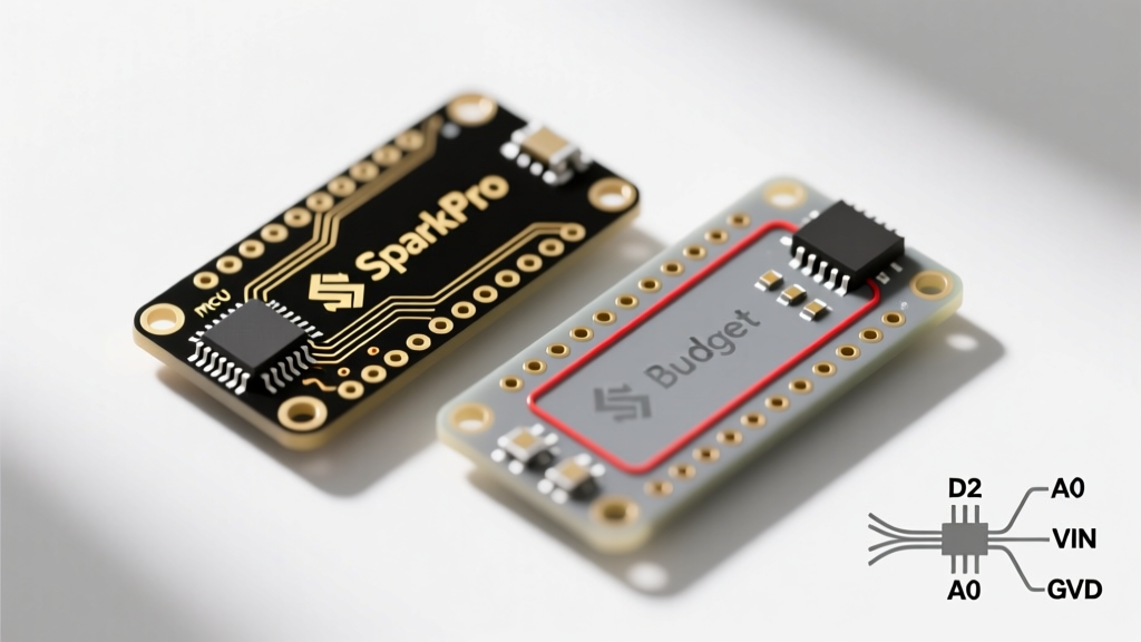
The market for ATmega32U4 development boards is heavily bifurcated. On one side, you have the original SparkFun Pro Micro (typically priced around $22 to $25). On the other, you have generic, unbranded clones available on Amazon and AliExpress for as little as $4 to $6 for a three-pack. While the silicon is identical, the supporting circuitry reveals massive quality disparities.
Comparison Matrix: SparkFun vs. Generic Clones
| Feature | Premium (SparkFun DEV-12640) | Budget (Generic Clone) |
|---|---|---|
| Price (Approx. 2026) | $24.95 | $4.50 (per unit in multi-pack) |
| Voltage Regulator | Micrel MIC5219 (High thermal tolerance) | Generic SOT-23-5 LDO (Prone to thermal shutdown) |
| USB Connector | Reinforced Micro-USB (or USB-C on newer revisions) | Standard Micro-USB (Poor solder joint adhesion) |
| Bootloader | Caterina (Optimized, auto-reset enabled) | Varies (Often requires manual reset during upload) |
| I2C Pull-ups | Often omitted to prevent bus conflicts | Omitted (External 4.7kΩ resistors mandatory) |
| Quality Control | 100% tested, flux cleaned | High failure rate on USB data lines |
The Voltage Regulator Trap
The most critical failure point on budget Pro Micro clones is the onboard Low Dropout (LDO) voltage regulator. The RAW pin is designed to accept an unregulated voltage (typically 5V to 12V), which the LDO steps down to 5V or 3.3V. SparkFun utilizes the MIC5219, which features internal current limiting and thermal shutdown, capable of handling moderate loads safely. Budget clones frequently use unmarked, ultra-cheap LDOs with a maximum current output of 150mA and virtually no heat dissipation. If you connect a 12V power supply to the RAW pin of a clone while drawing just 50mA from the 5V rail, the LDO must dissipate (12V - 5V) * 0.05A = 0.35W of heat. In a tiny SOT-23-5 package without a copper pour heatsink, the clone's regulator will overheat, trigger thermal shutdown, or permanently fail within minutes. Expert Advice: If using a budget clone in a 12V automotive or robotics environment, bypass the RAW pin entirely and use an external switching buck converter (like the LM2596 or MP1584) to feed a clean 5V directly into the VCC pin.
Native USB Quirks: When the Board Disappears
Because the ATmega32U4 handles USB communication natively via its firmware (rather than a dedicated hardware bridge), a bug in your sketch can crash the USB stack. When this happens, the board will disconnect from your PC, and the IDE will report that the port is unavailable. This is a common point of frustration for beginners transitioning from the Nano.
The Double-Tap Reset Recovery Trick:
If your Pro Micro vanishes from the Arduino IDE port list, do not panic. Locate the tiny RST (Reset) pad or pin on the board. Quickly short the RST pin to GND twice in rapid succession (within half a second). This forces the ATmega32U4 to bypass your corrupted sketch and enter the Caterina bootloader mode for exactly 8 seconds. During this 8-second window, the board will reappear in your IDE as a bootloader COM port, allowing you to flash a corrected sketch. For more on native USB recovery, consult the Arduino Getting Started Documentation.
Advanced Wiring: I2C Pull-Ups and SPI Routing
Understanding the Arduino Micro Pro pinout is only half the battle; knowing how to wire it for specific protocols is where projects succeed or fail.
I2C (TWI) Configuration
The I2C bus on the Pro Micro is mapped to D2 (SDA) and D3 (SCL). Unlike some larger development boards, neither the premium nor the budget Pro Micro boards include onboard I2C pull-up resistors. The internal AVR pull-ups (typically 20kΩ to 50kΩ) are too weak for reliable high-speed I2C communication, especially in electrically noisy environments or when using long wires. You must install external 4.7kΩ pull-up resistors connecting both SDA and SCL to the VCC line. If you are interfacing with 3.3V sensors (like the BME280) using a 5V Pro Micro, you will need a bidirectional logic level converter (such as the BSS138 MOSFET circuit) to prevent frying the sensor's I2C pins.
SPI Routing and the RXLED Conflict
SPI is essential for driving high-speed peripherals like TFT displays or SD card modules. On the Pro Micro, the SPI pins are broken out as D14 (MISO), D15 (SCK), and D16 (MOSI). However, the Slave Select (SS) pin presents a unique hardware quirk. On the ATmega32U4, the hardware SS pin is PB0, which the Pro Micro designers hardwired to the onboard RX LED. If your SPI library attempts to toggle the SS pin to manage chip selection, it will inadvertently flash the RX LED. While this rarely breaks functionality, it introduces minor parasitic capacitance and current draw on the SS line. For high-frequency SPI applications (above 4MHz), it is highly recommended to define a custom software SS pin (such as D10) in your code and physically wire your peripheral's CS pin to D10, leaving the hardware PB0/RXLED pin untouched.
Final Verdict: Which Should You Choose?
If you are building a one-off custom macro pad, a low-power data logger, or a prototype where budget is the primary constraint, the $4 generic clones are perfectly adequate—provided you respect their thermal limits and use external pull-ups. However, if you are designing a product for commercial deployment, integrating the board into a high-vibration environment, or require the SparkFun Pro Micro Hookup Guide level of reliability and support, the premium board's robust LDO and reinforced USB connector easily justify the 5x price premium. Always match your power delivery strategy to the specific hardware variant you hold in your hands.