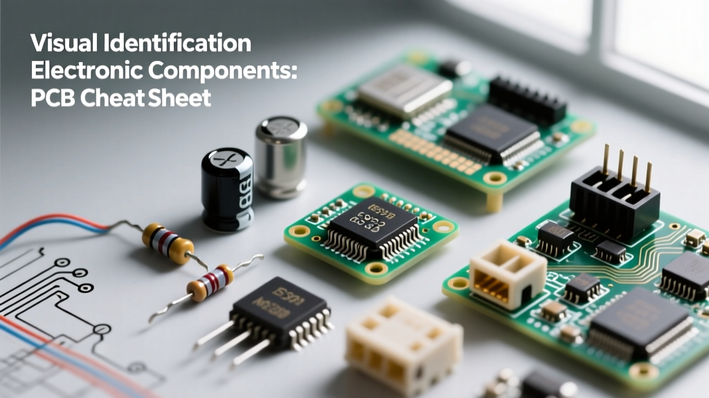

The Ultimate PCB Cheat Sheet for Component Identification
Whether you are reverse-engineering a legacy control board, debugging a modern IoT device, or performing failure analysis on a burnt power supply, the rapid identification of electronic components is the most critical first step in any diagnostic workflow. As of 2026, the industry's aggressive shift toward ultra-miniature 01005 and 008004 metric SMD packages has made visual inspection more challenging than ever. Relying solely on silkscreen designators is no longer sufficient; engineers must decode micro-markings, understand package topologies, and recognize subtle physical failure modes.
This reference guide serves as your definitive cheat sheet for the identification of electronic components on densely populated printed circuit boards (PCBs). We align our visual inspection criteria with the IPC-A-610 Acceptability of Electronic Assemblies standard, ensuring your diagnostic methodology meets professional manufacturing and rework benchmarks.
⚠️ ESD & Safety Warning: Before probing or visually inspecting any bare PCB under magnification, ensure the board is fully discharged. Use a verified ESD-safe mat and wrist strap. High-voltage DC bus capacitors in power supplies can retain lethal charges for weeks after power removal.
Master Silkscreen Designators & Visual Traits
Silkscreen designators (the white text printed on the PCB substrate) provide the first clue for component identification. Below is the universal matrix for standard designators, visual characteristics, and their most common failure modes.
| Designator | Component Type | Visual / Physical Traits | Primary Failure Mode |
|---|---|---|---|
| R | Resistor | Black/brown rectangular body (SMD) or color-banded cylinder (TH). | Open circuit due to thermal overstress; surface charring. |
| C | Capacitor | Tan/brown ceramic (MLCC), cylindrical aluminum electrolytic, or molded tantalum. | Short circuit (MLCC flex crack); electrolyte drying/venting. |
| L | Inductor / Ferrite | Thick molded body, visible copper wire winding, or solid dark grey ferrite. | Core saturation; internal wire breakage from vibration. |
| D | Diode | Cylindrical with a cathode band (TH) or small SMD with a white line. | Short circuit from reverse voltage breakdown or thermal runaway. |
| Q | Transistor / MOSFET | 3-pin SOT-23, 5-pin SOT-223, or large tabbed TO-220/D2PAK packages. | Gate oxide puncture; drain-source short from overcurrent. |
| U / IC | Integrated Circuit | Black epoxy body with silver pins (SOIC, QFN, BGA). Laser-etched top markings. | Internal silicon die failure; bond wire lift-off; BGA solder fatigue. |
| Y | Crystal Oscillator | Metallic silver cylindrical or rectangular SMD can with 2 or 4 pads. | Quartz element shattering from mechanical shock or drop. |
Decoding Passive Components: Beyond the Color Bands
Resistors & SMD Marking Codes
Through-hole resistors still utilize the standard 4-band or 5-band color code system. However, modern SMD resistors require knowledge of three distinct coding systems based on their tolerance and size:
- 3-Digit Code (5% Tolerance): The first two digits are significant figures, and the third is the multiplier. Example:
473= 47 × 10³ = 47,000Ω (47kΩ). - 4-Digit Code (1% Tolerance): The first three digits are significant figures. Example:
1002= 100 × 10² = 10,000Ω (10kΩ). - EIA-96 Code (1% Tolerance, 0603 size): Uses two numbers and a letter. The numbers represent a value from the EIA-96 lookup table, and the letter is the multiplier. Example:
01C. '01' equals 100, and 'C' equals 10². Therefore, 100 × 100 = 10kΩ.
Expert Tip: If an SMD resistor reads 000 or 0, it is a zero-ohm jumper, not a faulty component. These are frequently used to cross signal traces on single-layer PCBs.
Capacitors & The Polarity Trap
Identifying capacitor polarity is a frequent source of catastrophic failure during rework.
- Aluminum Electrolytic: The dark stripe with minus signs indicates the NEGATIVE terminal.
- Tantalum Capacitors (e.g., Kemet T491 series): The white or colored stripe indicates the POSITIVE terminal. Reversing polarity on a tantalum capacitor will cause it to ignite violently due to thermal runaway.
- MLCC (Multi-Layer Ceramic Capacitors): These are non-polarized. However, they rarely feature surface markings. Identification of an unmarked MLCC requires desoldering it and measuring it with an LCR meter, as visual sizing (e.g., 0402 vs 0603) only indicates physical dimensions, not capacitance.
Active Components & Semiconductor Marking Codes
Transistors and Diodes (SOT-23 & SOD-123)
Small Outline Transistor (SOT-23) packages are ubiquitous for BJTs and MOSFETs, but they are too small to print full part numbers. Manufacturers use 2-character or 3-character marking codes. For instance, the code 1AM on a SOT-23 package universally designates a 2N3904 NPN transistor. Similarly, 702 often designates a 2N7002 N-channel MOSFET.
For Zener and Schottky diodes in SOD-123 packages, the cathode band is always present. Because codes like Z3 or S4 are highly manufacturer-dependent, you must cross-reference the code alongside the package type using a dedicated database like AllDataSheet or the manufacturer's specific SMD code manual.
Integrated Circuits (ICs) and Date Codes
IC identification relies on recognizing manufacturer logos and deciphering the top-mark nomenclature. According to Texas Instruments packaging standards and similar industry norms, a typical IC marking includes:
- Manufacturer Logo: Identifies the fab (e.g., TI, STMicroelectronics, NXP, Microchip).
- Base Part Number: The core model (e.g.,
TPS5430,STM32F103). - Lot/Traceability Code: Internal factory batch numbers.
- Date Code (YYWW): A 4-digit code representing the Year and Work Week. A code reading
2542means the chip was manufactured in the 42nd week of 2025.
Counterfeit Warning: If the date code predates the board's known manufacturing date by several years, or if the laser etching feels shallow and easily scratches off with isopropyl alcohol, the IC may be a remanufactured counterfeit. Always verify lot codes with the original manufacturer when debugging critical aerospace or medical hardware.
Essential Tools for the 2026 Workbench
Visual identification must be paired with electrical verification. Relying on eyesight alone is insufficient for modern micro-electronics. Equip your bench with these specific instruments:
- Digital Multimeter (DMM): The Fluke 87V Industrial Multimeter (approx. $420) remains the gold standard for its low-impedance (LoZ) mode, which prevents ghost voltage readings when identifying floating CMOS inputs.
- LCR Meter: For identifying unmarked MLCCs and verifying inductor saturation. The Der EE DE-5000 (approx. $130) or the Keysight U1733C (approx. $300) provide precise equivalent series resistance (ESR) and capacitance readings at 100kHz.
- Stereo Microscope: The AmScope SM-4TP (approx. $250) with a 10x/20x objective and ring light is essential for reading EIA-96 codes and inspecting BGA solder joints for micro-fractures.
- Thermal Camera: A FLIR C5 or similar handheld thermal imager helps identify shorted components by visualizing localized heat dissipation when a board is powered via a current-limited bench supply.
Failure Modes & Edge Cases in Visual ID
Sometimes, identifying a component means identifying how it died. Recognizing physical degradation provides immediate clues to the circuit's failure mechanism:
- MLCC Flex Cracks: Ceramic capacitors placed too close to the PCB edge or V-score lines often develop invisible micro-cracks due to board flexure. Visually, this may present as a faint hairline fracture near the termination pads, but electrically, it manifests as a dead short or intermittent capacitance drop.
- Tin Whiskers: On legacy or RoHS-exempt boards, pure tin finishes can grow microscopic crystalline structures (whiskers) that bridge adjacent SMD pads, causing erratic shorts. These require 40x magnification to identify.
- Electromigration in Fuses: PPTC (Polymeric Positive Temperature Coefficient) resettable fuses may look physically intact but fail to reset if subjected to repeated over-current events. Always verify PPTCs with a DMM; a reading significantly higher than the datasheet's specified R1max indicates permanent polymer degradation.
Frequently Asked Questions (FAQ)
How do I identify a burnt SMD resistor?
If the markings are completely charred, visual identification is impossible. You must desolder the component to isolate it from the parallel circuit paths, then measure it with an LCR meter. If it reads open (OL), check the schematic or trace the copper pathways to determine its function (e.g., a pull-up resistor will connect to a known VCC rail, while a current-sense resistor will sit in series with a power MOSFET source pin).
Are there apps that can identify electronic components from a photo?
While AI-powered visual recognition apps have improved by 2026, they are highly unreliable for SMD components due to the lack of surface markings on MLCCs and the dense, overlapping nature of PCB layouts. They can occasionally identify large through-hole components or specific IC packages, but manual cross-referencing of marking codes and datasheets remains the only professional standard.
What is the difference between a ferrite bead and an inductor?
Visually, they are nearly identical (often both using molded 0805 or 1206 packages). However, electrically, an inductor (designated 'L') is designed to store energy and has a specific inductance value (e.g., 10µH). A ferrite bead (designated 'FB' or 'L') is designed to dissipate high-frequency noise as heat and is rated by its impedance at 100MHz (e.g., 600Ω @ 100MHz). You can differentiate them using an LCR meter: inductors will show a stable inductance reading, while ferrite beads will show a highly resistive impedance curve at high frequencies.


