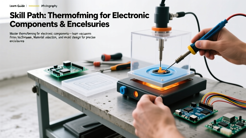

The Skill-Building Path to Custom Electronics Packaging
When prototyping custom PCBs or producing small-batch consumer electronics, off-the-shelf enclosures rarely fit perfectly. 3D printing is excellent for iteration, but it lacks the isotropic strength, optical clarity, and production speed required for final packaging. This is where thermoforming for electronic components becomes an indispensable skill in the modern maker's arsenal. By heating a thermoplastic sheet until pliable and drawing it over a mold using vacuum pressure, engineers can create bespoke blister packs, conformal covers, and rugged enclosures in a matter of minutes.
As of 2026, the accessibility of desktop vacuum formers has bridged the gap between DIY garages and professional manufacturing floors. However, achieving crisp, professional results requires more than just pushing a button. This guide outlines a progressive skill-building path, taking you from material fundamentals to advanced mold engineering and failure-mode troubleshooting.
Phase 1: Material Science and Thickness Selection
The foundation of successful thermoforming for electronic components lies in matching the polymer to the environmental and mechanical demands of your device. Not all plastics behave identically under heat and vacuum.
| Material | Forming Temp Range | Best Electronics Use Case | Shrinkage & Optical Clarity |
|---|---|---|---|
| PETG | 160°C - 180°C | Blister packs, clear ESD-safe covers | Low shrinkage, excellent clarity |
| ABS | 170°C - 190°C | Rugged opaque enclosures, internal trays | Medium shrinkage, opaque |
| Polycarbonate (PC) | 190°C - 210°C | High-impact transparent faceplates | High shrinkage, glass-like clarity |
| Kydex (ABS/PVC) | 160°C - 175°C | Holsters, heavy-duty protective shells | Low shrinkage, matte/satin finish |
Thickness Guidelines for Electronics
- 0.020" (0.5mm): Ideal for lightweight blister packaging, anti-static component trays, and dust covers. Requires minimal heat and forms rapidly.
- 0.040" (1.0mm): The sweet spot for structural enclosures, wearable device housings, and custom faceplates. Offers a balance of rigidity and detail resolution.
- 0.060" (1.5mm) to 0.080" (2.0mm): Reserved for heavy-duty tool cases, drone chassis covers, and automotive electronics housings. Requires high-wattage heating elements and deep-draw vacuum capabilities.
Phase 2: Equipment Dynamics and Vacuum Pressure
A common beginner mistake in thermoforming for electronic components is underestimating the required vacuum pressure. Electronics molds often feature fine details like ventilation slots, screw bosses, and text embossing. To pull plastic tightly into these crevices, you need significant negative pressure.
Expert Insight: A standard wet/dry shop vacuum generates high airflow but low static pressure (typically 4 to 6 inHg). For crisp electronic enclosures, you need a dedicated vacuum pump capable of pulling 25 to 29 inHg (inches of mercury). According to the Formlabs Guide to Vacuum Forming, insufficient vacuum pressure is the leading cause of poor detail reproduction and webbing in small-batch manufacturing.
Desktop vs. Industrial Setups in 2026
For hobbyists and small engineering teams, all-in-one desktop units like the Mayku FormBox (retailing around $699) remain the gold standard. These units use a shop-vac for the initial pull but rely on a specialized platen design to maximize the efficiency of the suction. For higher volume, DIY vacuum tables built with 3 CFM HVAC pumps and laser-cut MDF platens offer superior draw depth at a lower long-term cost, though they require significant calibration.
Phase 3: Mold Engineering for PCBs and Components
The mold is the most critical variable in the thermoforming process. Electronic components feature sharp right angles, deep pockets, and delicate geometries. If your mold is poorly designed, the plastic will tear, thin out, or lock onto the mold permanently.
The 5 Rules of Thermoform Mold Design
- Eliminate Sharp Corners: Plastic stretches and thins as it wraps around a corner. All external mold corners must have a minimum radius of 3mm. Internal corners (where the plastic goes into a pocket) should have a minimum radius of 1.5mm.
- Mandate Draft Angles: Never design vertical walls. Apply a minimum draft angle of 3° to 5° to all vertical surfaces. This allows the formed plastic to release from the mold without vacuum-locking or scuffing.
- Zero Undercuts: Standard thermoforming cannot handle undercuts. If your electronic enclosure requires a snap-fit lip, you must design a two-part mold or use post-forming CNC routing.
- Vacuum Hole Placement: Drill vacuum holes (0.5mm to 0.8mm diameter) in the deepest recesses and tightest corners of your mold. Space them roughly 15mm apart across flat planes to ensure even air evacuation.
- Material Selection for Molds: Standard 3D printed PLA softens at 60°C. The radiant heat from a 180°C PETG sheet will warp a PLA mold after just two or three pulls. For production runs, use High-Temp Resin (e.g., Siraya Tech Tenacious or Formlabs High Temp), CNC-machined MDF, or cast epoxy.
Phase 4: The Execution Sequence
Mastering the physical workflow requires timing and observation. Here is the step-by-step sequence for forming a 0.040" PETG enclosure for a custom microcontroller board.
Step 1: Clamping and Pre-Heating
Secure the PETG sheet tightly in the clamping frame. Any slack will result in uneven heating. Turn on the heating element (typically a 1200W quartz array). For 0.040" PETG, target a surface temperature of 165°C. As noted by Plastics International PETG Specifications, overheating will cause the polymer chains to break down, leading to bubbling and severe webbing.
Step 2: Identifying the 'Sag Point'
Do not rely solely on a timer. Watch the plastic. When it reaches the optimal forming temperature, it will begin to 'sag' or drape downward under its own weight. This is your visual cue. The sheet should look slightly glossy and feel like thick rubber.
Step 3: The Drape and Vacuum Pull
Lift the heated sheet over the mold and pull the frame down in one smooth, decisive motion. Simultaneously engage the vacuum pump. The plastic will snap tightly against the MDF or resin mold. Hold the vacuum for 10 to 15 seconds to allow the plastic to cool below its glass transition temperature.
Troubleshooting Matrix: Failure Modes and Corrections
Even experienced engineers encounter defects when thermoforming for electronic components. Use this diagnostic matrix to correct issues on the fly.
| Defect | Visual Symptom | Root Cause | Corrective Action |
|---|---|---|---|
| Webbing | Folds and wrinkles in deep corners | Plastic was too hot; mold geometry too complex | Reduce heat time by 10%; increase corner radii on mold; use a plug assist. |
| Chill Marks | Dull, rough patches on the plastic surface | Mold was too cold; premature freezing of plastic | Pre-heat the mold to 40°C-50°C before forming; increase vacuum hole density. |
| Thinning / Tearing | Translucent, fragile spots on tall features | Sharp corners on mold; excessive draw depth | Sand mold edges to a 3mm radius; reduce mold height; switch to a thicker sheet. |
| Vacuum Locking | Plastic refuses to release from the mold | Insufficient draft angle; trapped air | Redesign mold with a 3° draft; add more micro-vent holes to break the seal. |
Advanced Technique: Plug Assists for Deep Enclosures
When designing deep enclosures for tall components like electrolytic capacitors or large heatsinks, standard vacuum forming will cause severe thinning at the top edges. The plastic stretches across the void before being pulled down into the mold. To solve this, introduce a plug assist.
A plug assist is a secondary, slightly smaller mold (often carved from high-density foam or wood) attached to a handle. As the hot plastic is draped over the main mold, you physically push the plug assist into the center of the sheet, mechanically pre-stretching the material downward before engaging the vacuum. This technique distributes the plastic thickness evenly across deep draws, ensuring your electronic enclosure maintains structural integrity at the base.
Conclusion: Scaling Your Prototyping Workflow
Thermoforming for electronic components bridges the gap between one-off 3D printed prototypes and expensive injection-molded production runs. By mastering material temperatures, investing in adequate vacuum pressure, and adhering to strict mold design rules, you can produce professional-grade enclosures and packaging in your own workshop. As you progress through this skill path, experiment with multi-layer forming and ESD-safe materials to push the boundaries of your custom electronics manufacturing.