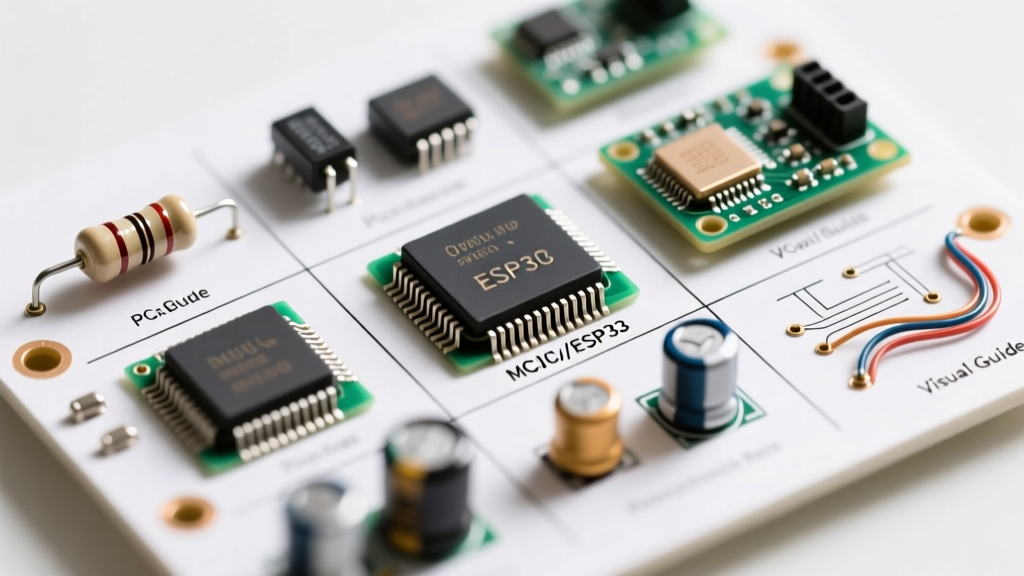

The Ultimate PCB Component Identification Matrix
Whether you are reverse-engineering a legacy motherboard, troubleshooting a dead consumer device, or designing your first custom PCB, the ability to rapidly identify electronic components is the foundational skill of any electrical engineer or technician. Modern printed circuit boards (PCBs) are densely packed with surface-mount devices (SMDs) that lack the clear visual cues of older through-hole parts. This reference cheat sheet provides the exact silkscreen prefixes, physical characteristics, and failure modes you need to accurately map out any circuit board in 2026.
| Component Type | Silkscreen Prefix | Schematic Symbol | Common SMD Packages | Primary Function |
|---|---|---|---|---|
| Resistor | R (e.g., R14, R102) | Zig-zag line or rectangular box | 0201, 0402, 0603, 0805 | Current limiting, voltage division, pull-up/pull-down |
| Capacitor | C (e.g., C22, C9) | Two parallel lines (one curved if polarized) | MLCC (0402-1206), Tantalum (A-V case) | Decoupling, filtering, energy storage, timing |
| Inductor / Ferrite | L or FB (e.g., L3, FB1) | Coiled loops | Shielded drum, molded chip | Choking high-frequency noise, power conversion |
| Diode | D (e.g., D5, D12) | Triangle pointing to a line | SOD-123, SOD-323, SMA, SMB | Rectification, reverse polarity protection, clamping |
| Transistor / MOSFET | Q (e.g., Q1, Q7) | Three-terminal device with arrow | SOT-23, SOT-223, TO-252 (DPAK) | Switching, amplification, power regulation |
| Integrated Circuit (IC) | U or IC (e.g., U4, IC1) | Rectangle with multiple pin lines | SOIC-8, QFP, QFN, BGA | Microcontrollers, logic gates, op-amps, power management |
Decoding Passive Components
Resistors and the Imperial vs. Metric Sizing Trap
When you identify electronic components like SMD resistors, you will notice they are tiny rectangular prisms, usually black with silver ends. The most confusing aspect for beginners is the sizing nomenclature. In the industry, SMD sizes are typically referred to by their imperial codes, but datasheets often use metric codes.
- 0402 (Imperial): Measures 0.04 x 0.02 inches. In metric, this is called 1005 (1.0 x 0.5 mm). This is the standard size for most consumer electronics in 2026.
- 0603 (Imperial): Measures 0.06 x 0.03 inches. In metric, this is 1608. Highly common in hobbyist and industrial boards.
- 01005 (Imperial): Measures 0.015 x 0.008 inches (0.4 x 0.2 mm). Found in modern smartphones and wearables; requires a high-quality microscope to identify and solder.
Expert Tip: SMD resistors do not have color bands. Instead, they use a 3-digit or 4-digit EIA code printed on top. A code of 103 means 10 followed by 3 zeros (10,000 ohms or 10kΩ). For values under 10 ohms, the letter 'R' acts as a decimal point (e.g., 4R7 = 4.7Ω). For a comprehensive breakdown of axial color bands, refer to the All About Circuits resistor color code guide.
The Capacitor Polarity Trap (Crucial Edge Case)
Misidentifying capacitor polarity is responsible for a massive percentage of beginner board-fry incidents and catastrophic component failures. You must distinguish between the two most common polarized capacitors:
- Aluminum Electrolytic (Through-Hole & SMD): These are cylindrical. The stripe on the body indicates the NEGATIVE (cathode) terminal. On SMD cans, the black semicircle painted on the top indicates the negative side.
- Tantalum Capacitors (SMD): These are typically yellow, orange, or black rectangular blocks. CRITICAL DIFFERENCE: The stripe or line on a tantalum capacitor indicates the POSITIVE (anode) terminal. Reversing a tantalum capacitor will cause it to short circuit, overheat, and potentially ignite.
Field Note: When testing MLCC (Multi-Layer Ceramic Capacitors) in-circuit with a multimeter, they will often read as a dead short (0 ohms). This is normal due to parallel circuit paths. To accurately measure capacitance and Equivalent Series Resistance (ESR), you must desolder the component or use an advanced in-circuit ESR meter.
Active Components: Semiconductors and ICs
Diodes and Transistors
Diodes are easily identified by a distinct band or line on one end of the package, which denotes the cathode (negative side). Current flows from the anode to the cathode. Common SMD packages include the SOD-123 (small, rectangular) and the larger SMA/SMB packages used for higher-current rectification like the ubiquitous SS34 Schottky diode.
Transistors (BJTs) and MOSFETs usually come in 3-pin packages like the SOT-23. While a generic SOT-23 BJT pinout is often Base (1), Emitter (2), Collector (3), never assume this without a datasheet. Manufacturers frequently swap pinouts for specific RF or high-speed switching transistors. To verify pinouts and junction health, use the diode-test mode on your multimeter. The Fluke guide on testing transistors provides an excellent step-by-step methodology for checking BJT junctions out-of-circuit.
Integrated Circuits (ICs) and Pin 1 Indicators
ICs range from simple 555 timers in SOIC-8 packages to massive Ball Grid Array (BGA) microprocessors. To correctly identify an IC's orientation, you must locate Pin 1. Manufacturers use several standardized markers:
- Laser Dot: A small indented or painted dot near one corner.
- Chamfered Edge: One corner of the IC body is cut at a 45-degree angle.
- Notch: A semi-circular cutout at the top edge of the IC (common on DIP and SOIC packages).
- Silkscreen Indicator: A dot or thick line printed on the PCB next to Pin 1.
Once you locate Pin 1, the pins are counted sequentially counter-clockwise around the perimeter of the chip. For BGA components, Pin 1 is usually located at the top-left corner (A1), and the grid is read via alphanumeric rows and columns.
SMD Marking Code Cheat Sheet
Because SMD transistors and diodes are too small for full part numbers, manufacturers use 2- or 3-character SMD codes. Identifying these requires cross-referencing. Below is a cheat sheet of highly common codes you will encounter:
| SMD Code | Actual Part Number | Component Type | Common Package |
|---|---|---|---|
| 1AM | MMBT3904 | NPN General Purpose Transistor | SOT-23 |
| 2A | MMBT3906 | PNP General Purpose Transistor | SOT-23 |
| 702 | BAT54S | Schottky Barrier Diode (Dual) | SOT-23 |
| A7W | BAV99 | High-Speed Switching Diode | SOT-23 |
| 431 | TL431 | Programmable Shunt Regulator | SOT-23 / SOIC-8 |
For obscure codes, do not guess. Use the DigiKey SMD Code Calculator or search the 's-manuals' database to prevent replacing a voltage regulator with a simple MOSFET, which will instantly destroy your load circuit upon power-up.
Essential 2026 Diagnostic Toolchain
To accurately identify and verify electronic components, visual inspection is only the first step. You need the right diagnostic hardware:
- Digital Multimeter (DMM): The Fluke 87V (approx. $420) remains the industry standard for its fast continuity beeper and reliable diode-test mode, which is essential for tracing PCB traces and identifying semiconductor junctions.
- LCR Meter: The DER EE DE-5000 (approx. $130) is a phenomenal bench tool. It automatically identifies whether a passive component is a resistor, capacitor, or inductor, and measures ESR to identify degraded electrolytic capacitors that visually look perfect but fail under load.
- Digital Microscope: For reading laser-etched SMD codes on 0402 and 0201 components, a Plugable USB 3.0 Digital Microscope (approx. $80) or an AmScope trinocular stereo microscope is mandatory. Ring lighting is critical to eliminate glare from solder joints.
Expert Troubleshooting and Failure Modes
When identifying components on a damaged board, be aware of physical failure modes that alter a component's appearance:
- MLCC Flex Cracking: Multi-Layer Ceramic Capacitors are brittle. If a PCB has been subjected to mechanical bending (e.g., a dropped laptop), MLCCs near mounting holes or board edges often develop microscopic cracks. They may look fine but will present as a dead short. Visual identification requires high-magnification inspection of the ceramic body edges.
- Counterfeit ICs: In the secondary market, ICs are frequently sanded down and re-lasered. If the silkscreen text on an IC looks perfectly uniform but the surface texture of the plastic package is slightly rougher than surrounding chips, or if the pin legs show uneven oxidation, suspect a reworked or counterfeit part.
- Thermal Discoloration: Resistors operating near their maximum power rating (e.g., a 1/4W resistor dissipating 0.2W) will slowly turn the PCB substrate brown over years of use. This is a thermal indicator, not necessarily a component failure, but it points you toward high-current paths in the circuit.
Mastering how to identify electronic components is a continuous process of pattern recognition. By combining visual silkscreen mapping, package size knowledge, and targeted electrical testing, you can confidently decode and repair even the most complex modern circuit boards.


