
The Hidden Cost of Dead Circuits: Component Failure Analysis
When a custom PCB fails to power on or a breadboard prototype exhibits erratic logic levels, the root cause rarely lies in the schematic design. More often than not, the culprit is a compromised physical part. Troubleshooting DIY electronic components requires moving beyond simple continuity checks and understanding the nuanced failure modes of modern semiconductors and passives. Whether you are dealing with electrostatic discharge (ESD) damage, thermal degradation, or the growing epidemic of counterfeit silicon, a systematic diagnostic approach is mandatory for any serious maker or electrical engineer.
The Counterfeit Crisis in DIY Sourcing
The democratization of hardware has led to a massive influx of third-party sellers on global marketplaces. Unfortunately, this has also triggered a surge in counterfeit electronic components. Fake parts range from harmless but out-of-spec clones to dangerous re-marked components that fail catastrophically under load. For instance, a 1A linear regulator sanded down and reprinted as a 3A model will inevitably trigger thermal runaway when pushed to its fake limits.
Visual and Physical Triage
Before applying power, subject your ICs and discrete semiconductors to a rigorous physical inspection:
- Surface Texture: Genuine ICs have a uniform, slightly textured epoxy finish. Counterfeiters often sand down old or lower-tier chips and apply a matte black coating to hide the tampering. Look for uneven edges or a surface that feels artificially smooth.
- Marking Permanence: Authentic chips use laser etching that physically alters the epoxy. Fakes often use cheap ink.
- Pin Oxidation and Re-tinning: Pull out a magnifying loupe. If the leads look overly shiny, uneven, or show signs of manual solder wicking, the parts may be salvaged from e-waste and re-tinned for resale.
- Weight Discrepancies: High-power components like MOSFETs and inductors have strict mass tolerances. A fake TO-220 package lacking the internal copper mass will feel noticeably lighter.
Expert Field Test: Rub the black epoxy case of a suspicious IC with a cotton swab soaked in pure acetone. If the text smears, fades, or transfers to the swab, it is a reprinted counterfeit. Genuine laser-etched markings will remain completely unaffected by brief acetone exposure.
Essential Diagnostic Arsenal for 2026
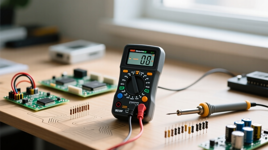
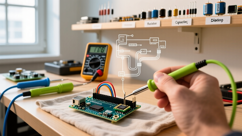
You cannot troubleshoot complex DIY electronic components with a $10 giveaway multimeter. Accurate diagnosis requires tools that can measure parasitic properties and thermal anomalies. Below is the recommended bench setup for serious component triage.
| Tool Category | Purpose & Diagnostic Value | Recommended Model (2026) | Approx. Cost |
|---|---|---|---|
| True-RMS Multimeter | Voltage drops, diode testing, basic continuity. | Fluke 117 or Brymen BM869s | $180 - $220 |
| LCR Meter | Measuring Equivalent Series Resistance (ESR) and parasitic inductance. | Der EE DE-5000 or Uni-T UT612 | $90 - $140 |
| Thermal Camera | Identifying shorted junctions and thermal runaway without contact. | InfiRay P2 Pro or FLIR ONE Edge | $250 - $350 |
| Component Tester | Quick automated pinout and hFE verification for discretes. | TC1 Multi-Function Tester | $25 - $40 |
Component-Specific Failure Modes & Testing
1. MOSFETs (e.g., IRFZ44N, IRLB8721)
Power MOSFETs frequently fail in DIY motor controllers and switching power supplies. The most common failure mode is gate oxide puncture caused by ESD or voltage spikes exceeding the Vgs(max) rating (typically ±20V). Once the microscopic oxide layer is breached, the gate becomes electrically connected to the source or drain, destroying the switching capability.
Step-by-Step Diode Mode Test (N-Channel):
- Set your multimeter to Diode Test mode.
- Place the red probe on the Source and the black probe on the Drain. You should read a forward voltage drop (typically 0.4V to 0.6V) representing the internal body diode.
- Reverse the probes (Red on Drain, Black on Source). The meter should read 'OL' (Open Loop).
- Test Gate to Source and Gate to Drain in both directions. Both must read 'OL'. If you read any continuity or low resistance between the Gate and any other pin, the MOSFET is dead and must be discarded.
2. Ceramic and Electrolytic Capacitors
Capacitors are the silent killers of circuit stability. While a shorted capacitor is easy to find (it reads near 0Ω), the more insidious failure is ESR drift in electrolytics and micro-cracking in multi-layer ceramic capacitors (MLCCs).
- Electrolytic ESR: A healthy 100µF 16V electrolytic capacitor should exhibit an ESR of less than 0.5Ω at 100kHz. If your LCR meter reads > 2.0Ω, the internal electrolyte has dried out, and the cap will cause severe ripple in power rails, leading to microcontroller brownouts.
- MLCC Piezoelectric Cracks: Large ceramic capacitors (like 10µF+ 0805 packages) are highly susceptible to board flexure. A microscopic crack can cause intermittent capacitance loss or high-leakage currents. Visually inspect the solder joints under a microscope for hairline fractures propagating into the ceramic body.
3. Linear Regulators (LM7805, AMS1117)
When a 5V rail measures 2.1V under a 50mA load, the linear regulator is likely suffering from junction degradation or internal thermal shutdown latch-up. To test, measure the input-to-output voltage differential while applying a known dummy load (e.g., a 50Ω power resistor). If the output voltage sags disproportionately compared to the datasheet's dropout voltage specification, the internal pass transistor is damaged.
Advanced Troubleshooting: Thermal Profiling
When dealing with complex boards where a shorted DIY electronic component is dragging down a power rail, visual inspection is insufficient. Enter thermal profiling. By injecting a low voltage, current-limited supply (e.g., 1V at 2A) into the shorted rail and observing the board with a thermal camera like the InfiRay P2 Pro, you can watch the faulty component light up. A shorted decoupling capacitor or a punctured Schottky diode will rapidly absorb the injected current and glow brightly on the thermal display, saving hours of tedious point-to-point multimeter probing.
Prevention: The Authorized Sourcing Framework
The most effective troubleshooting method is avoiding bad parts entirely. While marketplaces like Amazon or AliExpress offer convenience, they lack strict chain-of-custody controls. For mission-critical DIY projects, always source from authorized, franchised distributors who receive components directly from the manufacturers. Establishing accounts with industry leaders like Digi-Key or Mouser Electronics guarantees authenticity. Even for small hobbyist orders, the peace of mind and access to genuine datasheets far outweigh the slight premium in shipping costs.
FAQ: Quick Component Diagnostics
Why does my new microcontroller get instantly hot to the touch?
This is almost always caused by an I/O pin configured as an output driving HIGH while being physically shorted to ground on the PCB, or a reversed power polarity connection that has bypassed the internal protection diodes. Immediately cut power and check for solder bridges under the QFP/QFN pins using flux and a magnifying optic.
Can I test an SMD resistor without desoldering it?
You can test for an open circuit in-circuit. If your multimeter reads 'OL' on a resistor that should be 10kΩ, it is blown. However, you cannot accurately test for a short or a shifted value in-circuit, as the parallel resistance of the surrounding DIY electronic components will skew the reading. Desolder one pad to lift the component for an accurate measurement.
What causes a diode to fail short vs. fail open?
Diodes typically fail short when subjected to over-current conditions that melt the internal silicon junction. They tend to fail open when subjected to extreme voltage spikes that physically arc and vaporize the internal wire bond connecting the silicon die to the external lead.