
The Hidden Dangers of the Temp Sensor DS18B20
When engineers and DIYers select a temp sensor DS18B20 for thermal monitoring, they rarely consider 'safety' in the traditional sense. Operating at a mere 3.0V to 5.5V, the risk of lethal electric shock is non-existent. However, in the realm of embedded systems, industrial automation, and smart home infrastructure, safety translates to system integrity, fire prevention, and hardware protection. A poorly wired 1-Wire bus can lead to microcontroller GPIO burnout, phantom readings that disable critical thermal shutoffs, and localized thermal runaway in parasitic power configurations.
This guide dives deep into the electrical engineering best practices required to deploy the DS18B20 reliably, protecting both your hardware and the environments it monitors.
GPIO Protection: Pull-Up Resistor Sizing and Bus Capacitance
The 1-Wire protocol relies on an open-drain architecture. This means the microcontroller (MCU) and the sensor can only pull the data line (DQ) low; neither can actively drive it high. To return the line to a logic HIGH state, a pull-up resistor connected to VDD (3.3V or 5V) is mandatory. Sizing this resistor incorrectly is the most common cause of hardware damage and data corruption.
The Danger of Over-Sizing (Too Low Resistance)
If you use a pull-up resistor that is too small (e.g., 100Ω to 330Ω), the current flowing through the resistor when the MCU pulls the line LOW will exceed the GPIO pin's maximum sink capacity. For example, an ESP32 GPIO pin has an absolute maximum sink current of 28mA, but a recommended operating limit of 12mA. A 330Ω resistor on a 5V bus will attempt to sink 15.1mA continuously, potentially degrading the MCU's internal silicon over time and leading to catastrophic port failure.
The Danger of Under-Sizing (Too High Resistance)
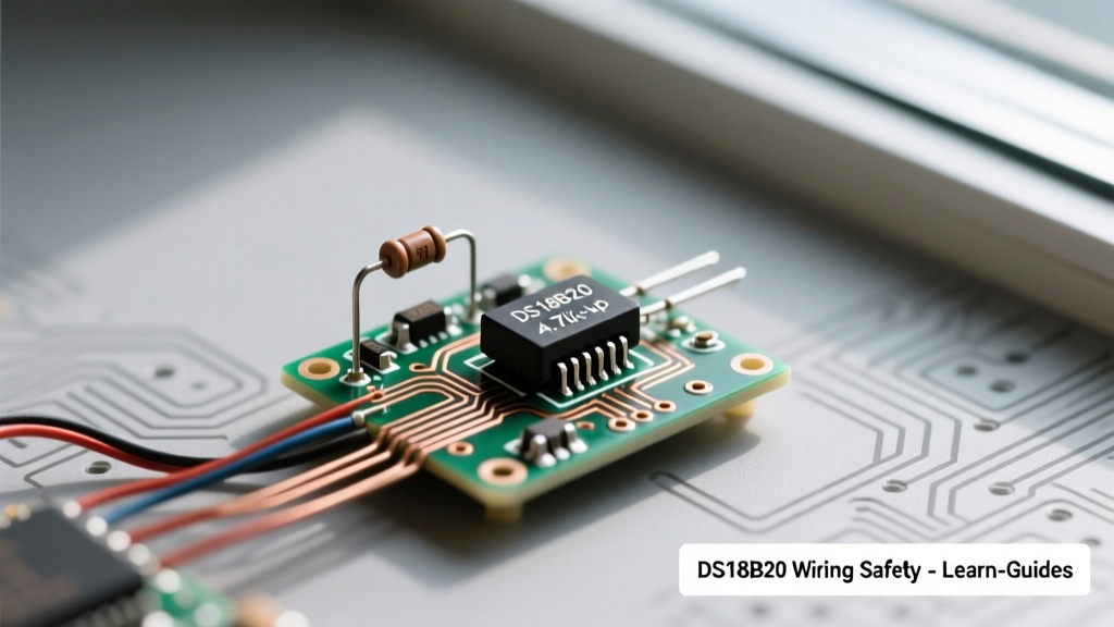
The standard recommendation found in the Analog Devices DS18B20 Datasheet is a 4.7kΩ resistor. While perfect for short breadboard jumper wires, this value becomes a safety hazard in long-run installations. Long cables introduce parasitic capacitance. If the bus capacitance exceeds 100pF, a 4.7kΩ resistor will cause the RC time constant to stretch the signal's rise time. The MCU will misinterpret slow-rising edges as logic errors, resulting in CRC (Cyclic Redundancy Check) failures. In a boiler or 3D printer thermal runaway protection system, a dropped packet means a missed over-temperature warning.
Expert Best Practice: For cable runs exceeding 10 meters, drop the passive pull-up resistor to 1kΩ or implement an active pull-up circuit using a MOSFET to provide a strong, temporary high-current pull-up during signal transitions without overloading the MCU GPIO during steady states.
Parasitic Power vs. External Power: Brownout and Thermal Risks
The DS18B20 offers a unique 'parasitic power' mode, allowing it to operate using only two wires (VDD tied to GND, and power stolen from the DQ line via an internal storage capacitor). While this saves copper, it introduces severe safety and reliability risks in modern low-power microcontrollers.
The 1.5mA Conversion Spike
During a 12-bit temperature conversion, the sensor requires up to 1.5mA of continuous current for 750 milliseconds. The MCU GPIO must source this current directly. Many modern battery-operated IoT MCUs (like certain STM32 or nRF52 series chips) have strict GPIO current limits or are driven by voltage regulators with tight transient response profiles. If the MCU cannot supply the 1.5mA spike, the local VCC rail sags, triggering a brownout reset. The system reboots, the safety monitoring loop is interrupted, and a thermal event goes unnoticed.
External Power Mode (The Safe Standard)
For any safety-critical application, always use the 3-wire external power mode. Connect Pin 1 to GND, Pin 2 to DQ (with pull-up), and Pin 3 to a dedicated 3.3V or 5V VDD rail. This ensures the sensor draws conversion current from the main power supply, bypassing the MCU's fragile GPIO limits entirely.
Environmental Safety: Waterproofing and Galvanic Corrosion
Most hobbyists purchase the pre-packaged, waterproof stainless-steel probe version of the temp sensor DS18B20. However, 'waterproof' is often a misnomer for cheap imports. The junction where the PVC cable meets the steel tube is typically sealed with basic epoxy or low-grade heat shrink.
Failure Mode: Capillary Action and Short Circuits
When deployed in humid environments, hydroponics, or outdoor weather stations, thermal cycling causes the cheap sealant to micro-crack. Water ingress travels via capillary action down the stranded wire. Once moisture reaches the internal TO-92 or SOIC package, galvanic corrosion bridges the VDD and DQ pins. This effectively feeds 5V directly back into the MCU's data line, bypassing the pull-up resistor and instantly frying the GPIO port or the MCU's internal protection diodes.
Mitigation Strategy: Always apply a secondary layer of marine-grade adhesive-lined heat shrink tubing over the factory seal, and use dielectric grease inside any connector housings.
Wiring Topologies and Safety Matrix
Choosing the right wiring topology is critical for maintaining data integrity in safety systems. Below is a comparison of deployment modes.
| Topology | Wiring Configuration | Safety & Reliability Rating | Best Use Case |
|---|---|---|---|
| External Power (Short) | 3-Wire (VDD, DQ, GND), 4.7kΩ Pull-up | High | Breadboarding, internal PCB, short cable runs (<3m) |
| External Power (Long) | 3-Wire, 1kΩ Pull-up or Active Pull-up | Critical / Industrial | Smart home HVAC, 3D printer enclosures, long runs (>10m) |
| Parasitic Power | 2-Wire (VDD to GND), DQ strong pull-up | Low (High Risk) | Space-constrained, non-critical logging only |
| Multi-Drop Bus | Multiple sensors on 1 DQ line | Moderate to High | Server rack monitoring (Requires careful capacitance management) |
The Counterfeit Threat: Identifying Fake Silicon
The market is currently flooded with counterfeit DS18B20 chips. These cloned ICs often fail catastrophically at temperature extremes and exhibit erratic power draw. More dangerously, they frequently return the 'power-on reset' default value of 85°C even when the actual environment is at 25°C, or when the sensor has completely failed. If your safety firmware does not explicitly check for the 85°C error code and the 0x0000 invalid reading, a counterfeit sensor will mask a genuine fire or overheating event.
How to Validate Your Sensors
- Check the ROM Code: Genuine Maxim/Analog Devices chips have specific family codes (0x28) and manufacturer IDs. Use a diagnostic sketch to read the full 64-bit ROM.
- Perform a Thermal Shock Test: Submerge the sensor in an ice-water bath (0°C). Counterfeits often exhibit massive non-linearity or fail to drop below 15°C.
- Verify the Scratchpad CRC: As noted in guides like the Random Nerd Tutorials ESP32 integration, always implement CRC-8 validation in your software. Fakes often generate corrupted scratchpad data under electrical noise.
Pre-Deployment Safety Checklist
Before integrating the temp sensor DS18B20 into a production or home-automation environment, verify the following:
- Software CRC Validation: Ensure your code rejects any reading that fails the 8-bit CRC check or returns exactly 85°C without a preceding power-cycle.
- Hardware Pull-Up Verification: Measure the DQ line with an oscilloscope. The rise time from LOW to HIGH must be under 1µs for standard speed 1-Wire communication.
- Decoupling Capacitors: Place a 100nF ceramic capacitor as close to the VDD and GND pins of the sensor as physically possible to suppress high-frequency EMI from nearby relays or motors.
- Wire Gauge: For runs over 5 meters, use a minimum of 22 AWG stranded wire to minimize voltage drop and ensure the pull-up resistor functions correctly at the sensor's physical location.
By treating the DS18B20 not just as a simple component, but as a critical node in your system's safety architecture, you eliminate phantom failures and ensure reliable thermal monitoring for years to come.