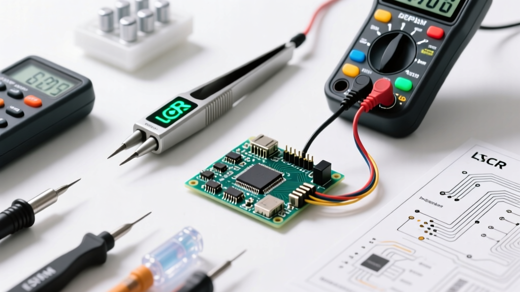

The Disconnect Between Schematics and Physical PCBs
When a printed circuit board (PCB) fails, the immediate instinct is to grab a multimeter and start probing. However, without a reliable reference, technicians frequently fall into the trap of misidentifying components, leading to misdiagnosis and accidental damage. The bridge between a theoretical schematic and a populated, multi-layer PCB is your ability to instantly translate abstract lines into physical reality. This is exactly where a comprehensive electronic components symbols and pictures pdf becomes an indispensable troubleshooting tool on your workbench.
In modern electronics repair, schematics often use generic IEEE or IEC symbols that omit critical physical details. A generic N-channel MOSFET symbol on a schematic might represent an IRLZ44N in a TO-220 package on one board, but a completely different logic-level chip in a surface-mount DPAK package on another. If you are troubleshooting a blown power stage and rely solely on memory, you risk injecting the wrong gate voltage or misinterpreting the pinout. Keeping a curated, offline electronic components symbols and pictures pdf on your diagnostic tablet ensures you never have to guess what you are looking at under the microscope.
Why Schematic-to-Physical Mismatches Cause Troubleshooting Blind Spots
The most common failure point in board-level diagnostics is the assumption that a schematic symbol perfectly dictates the physical footprint. In reality, design engineers frequently substitute components based on supply chain availability, leading to severe discrepancies between the service manual and the physical board.
The 'Generic Symbol' Problem
Consider a scenario where you are troubleshooting a switching power supply. The schematic shows a standard Schottky diode symbol. However, the physical board uses a dual-diode in a common-cathode SOT-23 package to save space. If your electronic components symbols and pictures pdf only shows the standard through-hole axial diode picture, you might probe the wrong pins, mistakenly concluding the diode is shorted when you are actually measuring across two different junctions.
According to industry repair standards, cross-referencing the physical package against a visual database is mandatory before applying thermal or electrical stress tests. You can verify standard symbol conventions and package variations through authoritative resources like the All About Circuits Reference Textbook, which outlines how schematic abstractions map to real-world physics.
The Troubleshooter’s Workflow: Leveraging Your PDF Reference
To maximize efficiency, integrate your PDF reference directly into your diagnostic workflow. Do not treat it as a passive document; treat it as an active diagnostic matrix.
- Visual Inspection & Silkscreen Matching: Use a digital microscope (like the Plugable USB 250x) to read the silkscreen designators (e.g., Q1, U4, C12). Cross-reference these designators with your schematic, then immediately pull up the corresponding page in your electronic components symbols and pictures pdf to verify the expected physical package.
- Pinout Verification: Before connecting your oscilloscope or multimeter, confirm the pin 1 indicator. The PDF should clearly show the physical orientation of the dot, notch, or thick silkscreen line relative to the schematic symbol's pin numbers.
- Thermal & Electrical Correlation: If a component is running hot (verified via a thermal camera like the FLIR C5, currently retailing around $550), check the PDF to see if the physical package has an exposed thermal pad. If the schematic symbol lacks a ground pin but the PDF picture shows a QFN package with a central thermal slug, you now know where to place your ground probe for accurate differential measurements.
- Substitution Identification: If the physical component text does not match the schematic BOM (Bill of Materials), use the visual database to identify the package type and search for cross-compatible replacements that match the original pinout.
Critical Component Cross-Reference Matrix
The following table highlights common discrepancies between schematic symbols, physical packages, and how to test them using a professional multimeter like the Fluke 87V ($450). For deeper component datasheets and visual footprints, technicians frequently rely on databases like Components101 to verify physical dimensions.
| Schematic Symbol | Common Physical Package | Typical Failure Mode | Multimeter Diagnostic Test |
|---|---|---|---|
| MLCC Capacitor (Non-polarized) | 0402, 0603, 0805 (Surface Mount) | Dendritic growth, micro-cracking causing dead shorts. | Measure resistance in-circuit. A reading below 10Ω on a non-power rail indicates a cracked dielectric. |
| Schottky Diode | SMA, SMB, SOT-23 (Dual) | Thermal runaway, junction short due to overvoltage spikes. | Diode test mode: Expect 0.2V - 0.4V forward drop. OL in reverse. A 0.00V reading confirms a dead short. |
| N-Channel MOSFET | TO-220, DPAK, SOIC-8 | Gate-oxide punch-through, drain-source short. | Check Gate-to-Source resistance. Should be high (MΩ). If Gate is shorted to Source, the driver IC is likely also destroyed. |
| Optocoupler | DIP-4, SOIC-4, SOP-4 | LED degradation (CTR drop), phototransistor leakage. | Test input pins as a standard diode (1.0V - 1.2V drop). Output pins should read OL in both directions when unpowered. |
Decoding Legacy and Obscure Notations
When repairing vintage audio amplifiers, legacy industrial controls, or older CRT-based equipment, you will encounter schematic symbols that defy modern conventions. A comprehensive electronic components symbols and pictures pdf must include both ANSI Y32.2 (US standard) and IEC 60617 (International standard) variations.
Expert Insight: In legacy American schematics, resistors are drawn as zigzag lines, and capacitors often feature a curved plate to denote the grounded or outer foil side. In modern IEC standards, resistors are simple rectangles, and the curved capacitor plate is largely abandoned. If you misinterpret a curved plate as a polarized electrolytic capacitor on a 1970s schematic, you might install a polarized part backward in a signal path, causing severe DC offset and blowing the output stage.
Having a visual cheat sheet that places the ANSI zigzag resistor directly next to the IEC rectangular resistor, alongside pictures of vintage carbon-composition resistors versus modern metal-film resistors, prevents catastrophic installation errors during restoration.
Edge Cases: The SOT-23 Pinout Trap
The SOT-23 is the most ubiquitous 3-pin surface mount package in electronics, and it is the source of more troubleshooting errors than almost any other footprint. The danger lies in the fact that the electronic components symbols and pictures pdf will show a standard 3-pin outline, but the internal silicon mapping varies wildly depending on the component type.
- NPN Bipolar Junction Transistor (e.g., 2N3904): Pin 1 is Base, Pin 2 is Emitter, Pin 3 is Collector.
- P-Channel MOSFET (e.g., BSS84): Pin 1 is Gate, Pin 2 is Source, Pin 3 is Drain.
- Voltage Regulator (e.g., LM340MPX-5.0): Pin 1 is Input, Pin 2 is Ground, Pin 3 is Output.
If you are tracing a fault and assume the SOT-23 component at Q1 is a BJT because of its position in the circuit, but it is actually a MOSFET, your multimeter's hFE (transistor gain) test will yield confusing results, and your bias voltage measurements will seem completely wrong. Always use your visual PDF to identify the exact part number printed on the component, then pull the specific datasheet. As noted in Fluke's official multimeter troubleshooting guides, verifying the expected semiconductor junction behavior against the specific component type is critical before declaring a part faulty.
Curating Your Offline Troubleshooting Library
Do not rely on a generic, low-resolution PDF downloaded from an obscure forum. Build your own high-fidelity electronic components symbols and pictures pdf using tools like Adobe Acrobat or Drawboard PDF. Include the following sections in your master document:
1. Active vs. Passive Identification
Include high-resolution macro photography of component markings. For example, show the difference between a ceramic capacitor (unmarked, tan/brown) and a tantalum capacitor (marked with a polarity stripe and capacitance value). Mistaking a polarized tantalum for a non-polarized ceramic during a rapid repair will result in an immediate, violent short circuit upon power-up.
2. IC Package Dimensions and Pin 1 Indicators
Dedicate pages to complex ICs. Show pictures of SOIC-8, TSSOP-16, and QFP-48 packages, explicitly highlighting how to locate Pin 1 using the laser-etched dot, the beveled edge, or the missing corner. Include the schematic symbol for standard logic gates (NAND, NOR, XOR) and map them to their common 74HC-series physical pinouts.
3. Transformer and Inductor Polarity
Flyback transformers and coupled inductors rely heavily on the 'dot convention' on schematics. Your PDF must include pictures of physical transformer bobbins showing where the manufacturer places the physical dot or uses colored wire (e.g., red for start, black for finish) to indicate phase. Reversing the phase on a flyback transformer in a switching power supply will cause the MOSFET to avalanche and fail instantly.
Final Thoughts on Diagnostic Accuracy
Troubleshooting is not just about measuring voltage; it is about accurately interpreting the physical reality of the board against the theoretical intent of the designer. By keeping a meticulously curated electronic components symbols and pictures pdf loaded on your workbench tablet, you eliminate guesswork, avoid destructive pinout errors, and drastically reduce your diagnostic time. In the fast-paced world of electronics repair, visual verification is the ultimate safeguard against costly mistakes.