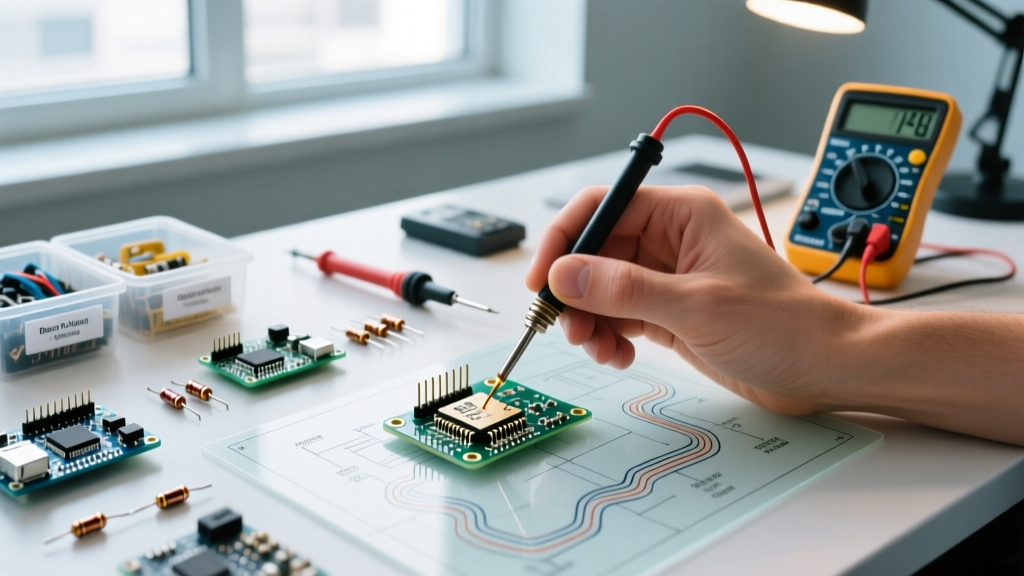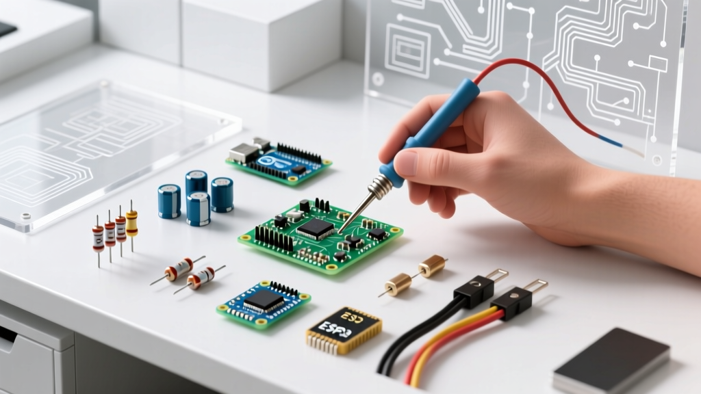

Introduction to PCB Component Identification
Designing, assembling, and troubleshooting printed circuit boards (PCBs) in 2026 requires more than just knowing what a resistor or capacitor does. Modern high-density designs demand a deep understanding of parasitic properties, thermal limits, package sizing nuances, and supply chain realities. Whether you are prototyping a low-power IoT sensor or repairing a high-frequency RF board, having a reliable reference is critical.
This comprehensive cheat sheet for electronic circuit board components bypasses the basic textbook definitions and focuses on actionable engineering data, real-world failure modes, and specific component selections used by professionals today.
The Core Passive Components Cheat Sheet
Passive components form the backbone of signal conditioning, power decoupling, and filtering. However, real-world passives exhibit parasitic behaviors that can derail a high-speed or high-power design.
| Component | Primary Function | Standard 2026 Models/Series | Hidden Parasitic Concern | Bulk Price Range | Common Failure Mode |
|---|---|---|---|---|---|
| Resistor | Current limiting, voltage division, pull-up/down. | Yageo RC Series, Vishay Dale CRCW | Parasitic inductance in high-frequency RF paths. | $0.001 - $0.01 | Resistance drift due to thermal overstress; open circuit from surges. |
| MLCC Capacitor | High-frequency decoupling, AC coupling. | Murata GRM Series, Samsung Electro-Mechanics | DC Bias Derating: A 10µF X5R cap may drop to 2µF at its rated voltage. | $0.005 - $0.04 | Short circuit from flex cracking (piezoelectric effect/board bending). |
| Electrolytic Cap | Bulk energy storage, low-frequency filtering. | Nichicon UWT, Panasonic FM/FR Series | High ESR (Equivalent Series Resistance) causing internal heating. | $0.08 - $0.50 | Electrolyte evaporation leading to capacitance loss and ESR spike. |
| Inductor | DC-DC converter energy storage, EMI choking. | Coilcraft XEL, TDK SPM Series | Saturation current (Isat) causing sudden inductance drop. | $0.15 - $0.80 | Core saturation leading to MOSFET overcurrent and thermal failure. |
Expert Insight on MLCCs: Never trust the nominal capacitance value of a ceramic capacitor at face value. According to Murata's MLCC design guidelines, engineers must consult the DC bias characteristic graphs. For a 5V rail, always select a capacitor with a 10V or 16V rating to maintain adequate effective capacitance.
Active Semiconductor Components Reference
Active components control electron flow and provide logic, amplification, and switching. Selecting the right active component requires balancing switching speed, thermal dissipation, and gate drive requirements.
Transistors & MOSFETs
When selecting a MOSFET for power switching, the distinction between standard and logic-level gate drives is a frequent trap for beginners.
- Standard MOSFETs (e.g., IRF520): Require 10V to 12V at the gate (Vgs) to fully turn on and achieve the lowest Rds(on). They will perform poorly and overheat if driven directly by a 3.3V microcontroller.
- Logic-Level MOSFETs (e.g., Infineon IRLZ44N, TI CSD17571Q5A): Designed to fully enhance at Vgs = 4.5V or even 2.5V. Always check the Rds(on) vs. Vgs graph in the datasheet, not just the threshold voltage (Vgs(th)), which only indicates when the device barely begins to conduct.
- GaN FETs (e.g., EPC2036): The 2026 standard for ultra-high-frequency switching (MHz range) in compact DC-DC converters, offering near-zero reverse recovery charge.
Integrated Circuits (ICs) & Microcontrollers
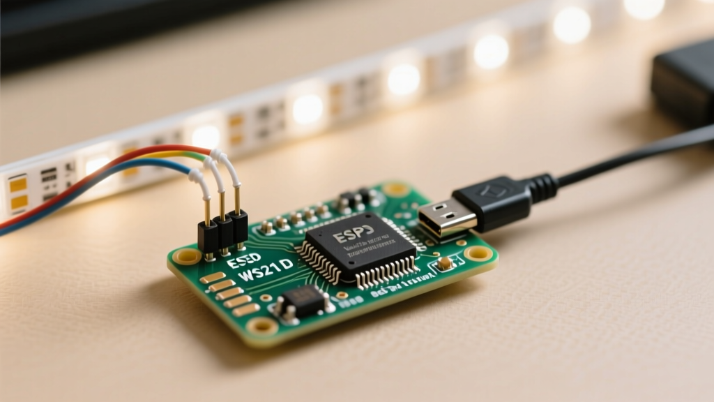
Modern embedded systems rely on highly integrated System-on-Chip (SoC) architectures. The Espressif ESP32-S3 remains a dominant force in 2026 for Wi-Fi/Bluetooth LE applications. Key specs for your cheat sheet:
- Architecture: Dual-core Xtensa LX7 @ 240 MHz.
- Native USB: Built-in USB OTG, eliminating the need for external UART-to-USB bridge ICs like the CP2102 or CH340.
- AI Acceleration: Vector instructions for neural network inference.
- Module Cost: ~$3.20 - $4.50 for the ESP32-S3-WROOM-1 module in low-volume production.
SMD Package Size Reference Chart (Imperial vs. Metric)
One of the most dangerous pitfalls in PCB design is the naming collision between Imperial and Metric SMD (Surface Mount Device) codes. A '0603' in the US usually means Imperial (0.06 x 0.03 inches), but in some Asian manufacturing contexts, it refers to Metric (0.6 x 0.3 mm). Always verify the units in your CAD software.
| Imperial Code | Metric Code | Dimensions (L x W in mm) | Handling & Assembly Notes |
|---|---|---|---|
| 01005 | 0402 | 0.40 x 0.20 | Microscopic. Requires automated pick-and-place and specialized microscopes. Prone to tombstoning. |
| 0201 | 0603 | 0.60 x 0.30 | Standard for high-density 2026 smartphones. Very difficult to hand-solder. |
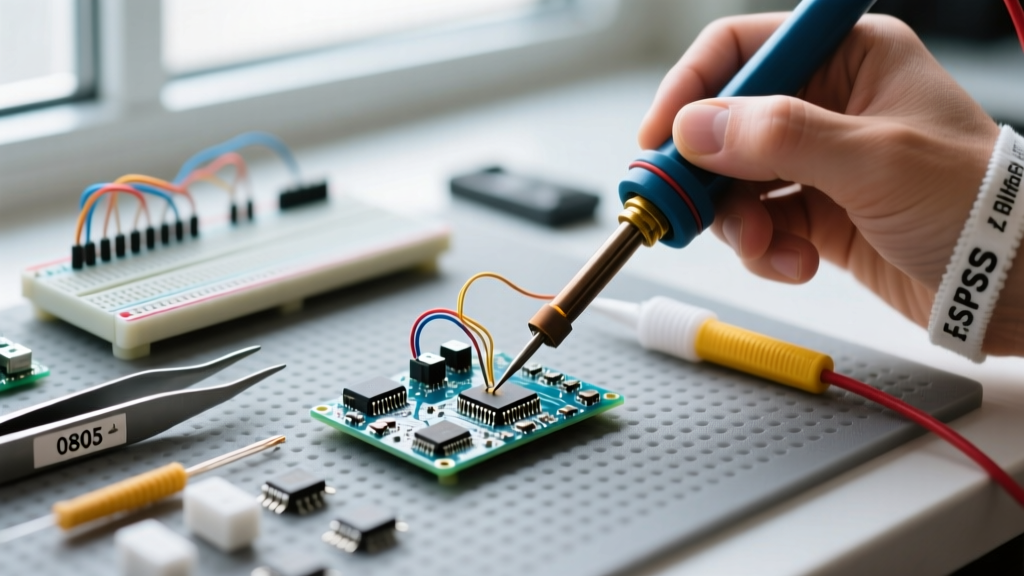
| 0402 | 1005 | 1.00 x 0.50 | The modern 'sweet spot' for consumer electronics. Hand-solderable with a fine tip and flux. |
| 0603 | 1608 | 1.60 x 0.80 | Highly recommended for DIY prototypes and hobbyist PCBs. Easy to rework. |
| 0805 | 2012 | 2.00 x 1.25 | Robust, handles higher power (typically 1/8W for resistors). Ideal for power rails. |
Electromechanical & Connectors Quick Guide
Connectors are often the point of failure in field-deployed electronics. Choosing the right pitch and retention mechanism is vital.
- JST SH (1.0mm pitch): Ubiquitous in micro-drones, wearables, and internal I2C/SPI wiring. Friction-lock only; vibrates loose in high-shock environments.
- Molex PicoBlade (1.25mm pitch): Superior to JST SH for internal wiring due to a more robust terminal retention mechanism.
- Phoenix Contact COMBICON (3.5mm / 5.08mm pitch): The gold standard for industrial terminal blocks. Features screw-clamp or spring-cage (Push-In) termination for high-vibration reliability.
Troubleshooting & Failure Analysis Matrix
When a board fails to power on, systematic isolation is required. Modern troubleshooting relies heavily on thermal imaging to detect shorts before applying full power.
Step-by-Step Short Circuit Detection
- Cold Resistance Check: Use a multimeter to measure resistance between VCC and GND. A reading below 5 ohms indicates a dead short.
- Diode Mode Testing: Switch the multimeter to diode mode. Measure the forward voltage drop across VCC and GND. Compare it to a known-good board. A drop of 0.00V confirms a hard short.
- Thermal Injection: Use a bench power supply to inject a low voltage (e.g., 1V) with a current limit of 1A into the VCC rail.
- Thermal Imaging: Scan the board with a thermal camera (like the FLIR C5 or the smartphone-attached InfiRay P2 Pro). The shorted component will illuminate as a hot spot within seconds.
Visual & Multimeter Failure Indicators
| Component Type | Visual Failure Sign | Multimeter Test | Probable Root Cause |
|---|---|---|---|
| Electrolytic Capacitor | Bulging top vent, crusty brown electrolyte leakage. | Capacitance mode reads 50%+ below nominal; ESR meter reads >2 ohms. | Thermal aging, excessive ripple current, or reverse polarity installation. |
| SMD IC / LDO Regulator | Micro-cracks on the package, burnt pin 1 indicator. | Diode mode on I/O pins shows 0.0V (short to ground). | Overvoltage transient (EOS) or electrostatic discharge (ESD) strike. |
| Power Inductor | Discolored core, melted adjacent solder mask. | Continuity check shows open circuit (infinite resistance). | Current exceeded the saturation limit, causing thermal runaway of the copper winding. |
Authoritative Sources & Further Reading
To maintain the highest standards in PCB assembly and component selection, always refer to current industry specifications. The IPC-A-610 standard remains the definitive visual quality acceptance guide for electronic assemblies, detailing exact solder fillet requirements and component mounting criteria. Furthermore, for power management component selection, consulting application notes from major semiconductor manufacturers like Texas Instruments MOSFET gate drive guides will prevent catastrophic switching failures in your power stages.
Keep this cheat sheet bookmarked in your lab. Proper identification, awareness of parasitic limitations, and systematic troubleshooting are what separate amateur tinkerers from professional electronics engineers.