
The Core Matrix: AC vs. DC Voltage Testing
When testing for voltage with multimeter equipment in the field, the most critical error occurs before the probes ever touch a conductor: selecting the wrong current type. Modern True-RMS digital multimeters (DMMs) like the Fluke 117 or Klein Tools MM400 feature distinct symbols and internal pathways for Alternating Current (AC) and Direct Current (DC). Misinterpreting these can lead to catastrophic meter failure or severe arc flash incidents.
Below is your quick-reference matrix for identifying, setting, and troubleshooting AC and DC voltage environments.
| Parameter | Alternating Current (AC) | Direct Current (DC) |
|---|---|---|
| Multimeter Symbol | V~ (or V with a solid/dashed line above) | V⎓ (or V with solid and dashed lines below) |
| Typical Sources | Mains outlets, HVAC systems, industrial panels, generators | Batteries, solar arrays, PCBs, automotive systems, UPS backups |
| Expected Ranges | 120V, 208V, 240V, 480V (US Standards) | 1.5V to 48V (Control); up to 800V (Solar/EV) |
| Polarity Sensitivity | None (Probes are interchangeable) | Strict (Red to positive, Black to negative; reversed yields negative reading) |
| Common Failure Mode | Measuring high-frequency VFD outputs with a standard DMM instead of a low-pass filter meter | Attempting to measure DC voltage while the dial is set to AC, resulting in a zero or erratic reading |
Safety First: Decoding CAT Ratings for Voltage Checks
A multimeter's voltage rating (e.g., 600V or 1000V) is only half the safety equation. The Measurement Category (CAT) rating dictates the tool's ability to survive transient overvoltages—massive, microsecond spikes caused by lightning strikes, motor startups, or capacitor switching. According to the Fluke Measurement Category Guidelines, a CAT III 600V meter is actually engineered to withstand an 8,000V transient spike, whereas a CAT II 1000V meter is only rated for a 6,000V spike. Therefore, CAT III 600V is significantly safer for industrial distribution panels than CAT II 1000V.
Quick-Reference CAT Boundary Table
| CAT Rating | Environment Boundary | Real-World Application |
|---|---|---|
| CAT II | Single-phase receptacle connected loads | Testing household outlets, appliances, portable tools, and standard 120V/240V branch circuits. |
| CAT III | Three-phase distribution, single-phase commercial lighting | Testing busbars, industrial control panels, HVAC hardwired connections, and sub-panel feeders. |
| CAT IV | Three-phase at utility connection, outdoor conductors | Testing primary feeders, utility meters, overhead lines, and main service entrance panels. |
Field Rule: Always use a meter and probe set that matches or exceeds the highest CAT environment you will enter. Never use CAT II rated probes on a CAT III panel, even if the meter itself is CAT III rated. The entire measurement chain must be certified.
Step-by-Step Execution: Testing for Voltage with Multimeter
Speed in the field should never compromise the NFPA 70E electrical safety standard. Follow this rigid protocol every time you test for voltage.
1. Dial and Lead Configuration
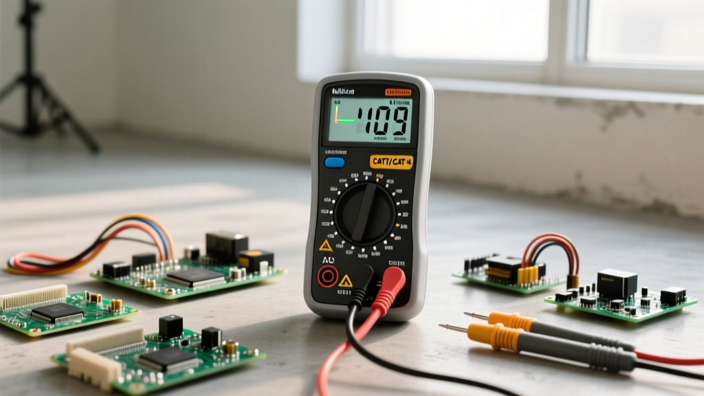
- Insert Leads: Black lead into the COM (Common) jack. Red lead into the V/Ω (Volts/Ohms) jack. Never leave the red lead in the Amps (A or mA) jack when testing voltage; this creates a dead short and will cause an explosive arc flash.
- Set the Dial: Select V~ for AC or V⎓ for DC. If using a manual-ranging meter, set it to the highest expected voltage range (e.g., 600V) before testing.
- Inspect Probes: Check for cracked insulation, exposed wire, or melted tips. Ensure your fingers are positioned strictly behind the tactile finger guards on the probe shafts.
2. The "Live-Dead-Live" Verification Protocol
This three-step verification is mandated by OSHA and the NFPA to ensure your meter hasn't suffered a silent internal failure (like a blown fuse or dead battery) that could give you a false "dead" reading on a live circuit.
- LIVE: Test your multimeter on a known, verified live voltage source (e.g., a dedicated outlet tester or a known live breaker). Confirm the meter reads the expected voltage.
- DEAD: Test the target circuit or component you are attempting to verify as de-energized. Test phase-to-phase, phase-to-ground, and phase-to-neutral. The reading must be zero.
- LIVE: Immediately return to the known live source to verify the meter is still functioning correctly and didn't fail during the previous step.
Troubleshooting Anomalies: Ghost Voltage and OL Readings
When testing for voltage with multimeter devices, you will inevitably encounter readings that seem to defy logic. Understanding the physics behind these anomalies prevents unnecessary troubleshooting and misdiagnosis.
The Phantom Menace: Ghost Voltage
If you test a disconnected wire in a multi-conductor conduit and read 40V to 90V AC, you are likely seeing ghost voltage (capacitive coupling). High-impedance digital multimeters (typically 10 Megohms) are so sensitive that they pick up stray electromagnetic fields from adjacent live wires in the same raceway.
The Fix: Switch your DMM to Low Impedance (LoZ) mode if equipped (found on models like the Fluke 117). LoZ drops the meter's internal resistance to roughly 3 kilohms, bleeding off the phantom capacitive charge and displaying the true 0V reading. Alternatively, use a solenoid voltage tester (often called a 'Wiggy'), which inherently draws enough current to ignore ghost voltages.
Decoding the "OL" Display
"OL" stands for Over Limit (or Open Loop, depending on the manufacturer). When testing voltage, an OL reading means the voltage present exceeds the maximum range currently selected on the dial.
- On Manual Ranging Meters: If you are set to the 20V scale and test a 120V outlet, the meter will display OL. Simply turn the dial to the 200V or 600V scale.
- On Auto-Ranging Meters: If an auto-ranging meter displays OL while set to voltage, the voltage exceeds the meter's absolute maximum rating (usually 1000V AC/DC). Stop testing immediately. You may be probing a medium-voltage utility line or experiencing a massive transient spike.
Internal Anatomy: Why HRC Fuses Matter
A critical, often overlooked aspect of safely testing for voltage is the multimeter's internal protection. Premium electrical multimeters utilize High Rupturing Capacity (HRC) ceramic fuses filled with quartz sand. If a user accidentally tests voltage with the leads in the current (Amps) jacks, a massive short circuit occurs. A standard glass fuse would vaporize, sustaining a plasma arc that could explode the meter in the user's hands. An HRC fuse, however, melts and the surrounding sand instantly absorbs the thermal energy, quenching the arc flash inside the sealed ceramic tube. Always verify your replacement fuses are exact OEM HRC specifications—never bypass a blown fuse with a wire or substitute it with a cheap glass alternative from a hardware store.
Pro-Tips from the Field: Minimizing Arc Flash Risks
Even with a CAT IV rated meter, the physical act of probing live busbars carries inherent risk. Implement these advanced field techniques to mitigate danger:
- Use Alligator Clips or Probe Grippers: Whenever possible, clip onto the test points before energizing the circuit. This removes your hands from the blast zone when the current hits.
- The One-Hand Rule: When probing live, high-energy circuits where clipping isn't possible, keep one hand in your pocket or behind your back. If you touch a live conductor and a grounded surface simultaneously with two hands, the current path crosses your heart, leading to fatal ventricular fibrillation. Keeping one hand isolated forces any potential shock to travel down your arm and to your boots, bypassing the chest cavity.
- Wear Proper PPE: Refer to NFPA 70E tables. Testing exposed 480V panels typically requires a minimum of Category 2 arc flash clothing (8 cal/cm²), voltage-rated rubber insulating gloves with leather protectors, and an arc-rated face shield.
Mastering the art of testing for voltage with multimeter tools is a blend of theoretical knowledge and rigid physical discipline. Keep this cheat sheet in your tool bag, respect the CAT boundaries, and never trust a circuit until you have personally verified it with the Live-Dead-Live protocol.