
Prototyping electronic circuits is an exciting process, but combining a breadboard and power supply without respecting physical and electrical limits is a recipe for disaster. While solderless breadboards are indispensable for rapid iteration, they were never designed to handle high power. Mismanaging voltage and current in a prototyping environment leads to melted ABS plastic, fried integrated circuits, ground loops, and wildly inaccurate sensor readings.
In this comprehensive guide, we will explore the hidden physics of breadboard contacts, establish hard safety boundaries, and outline the best practices for configuring your power supply to protect both your components and your workspace.
The Hidden Physics of Contact Resistance
To understand safety limits, you must first understand the mechanical reality of a solderless breadboard. Inside the plastic housing, rows of phosphor bronze or nickel-plated beryllium copper spring clips grip your component leads. While these clips provide excellent temporary connections, they introduce contact resistance.
A typical breadboard contact exhibits a resistance between 10mΩ and 50mΩ. When current flows from a power supply, through a jumper wire, into the breadboard rail, and out to a component, it passes through multiple contact points. If a path includes four contact interfaces, the total added resistance could easily reach 100mΩ to 200mΩ.
The Math Behind the Melt: According to Joule's first law (P = I²R), pushing just 2 Amps through a 100mΩ path dissipates 0.4 Watts of heat. Because this heat is generated inside a microscopic contact area encased in ABS plastic (which begins to soften and deform at roughly 105°C), the localized temperature spike can permanently warp the breadboard housing and oxidize the metal clips, leading to a cascading failure of the connection.
Hard Boundaries: Voltage and Current Limits
When setting up your breadboard and power supply, you must operate within strict manufacturer boundaries. While specifications vary slightly between premium brands like Global Specialties and generic imports, the following thresholds are universally accepted in professional engineering environments.
Current Limits
- Standard Signal Contacts: Maximum 1 Amp continuous. Exceeding this risks overheating the internal clips.
- Power Rails (Red/Blue lines): Maximum 2 to 3 Amps continuous. The power rails use longer, continuous metal strips, but the entry points where your jumper wires connect are still vulnerable to the same contact resistance heating.
- Peak vs. Continuous: Breadboards can handle brief current spikes (e.g., a motor starting up) slightly above these limits, but continuous DC draw must remain under the 1A per contact threshold.
Voltage Limits and Arcing
Most engineers assume breadboards can handle any voltage up to the power supply's maximum. This is false. The standard pitch of a breadboard is 0.1 inches (2.54mm), with an internal air gap of roughly 1mm between adjacent rows. At voltages exceeding 30V DC, the risk of electrical arcing across dust, flux residue, or humidity increases dramatically. For high-voltage prototyping (e.g., Nixie tubes or AC mains), solderless breadboards must never be used.
Selecting and Configuring Your Power Supply
The type of power supply you pair with your breadboard dictates your safety margin. Wall-wart adapters and raw lithium-ion batteries lack the immediate protection required for prototyping. A dedicated bench power supply or a high-quality programmable buck module is mandatory for safe development.
The Lifesaver: Over-Current Protection (OCP)
When configuring a bench supply (such as a Rigol DP832 or Korad KA3005P), always enable and configure the Over-Current Protection (OCP) before turning on the output. If you accidentally bridge VCC to GND with a misplaced jumper wire, a raw power supply will dump its maximum current (often 5A to 30A) into the breadboard, instantly vaporizing 22 AWG jumper wires and melting the plastic housing.
Best Practice: Set your OCP threshold just 20% above your circuit's expected maximum draw. If your microcontroller and sensors are calculated to draw 400mA, set the bench supply OCP to 500mA. This ensures the supply instantly cuts power in the event of a short circuit.
Constant Voltage (CV) vs. Constant Current (CC) Modes
Ensure your supply is operating in CV mode for standard logic circuits. If the supply accidentally enters CC mode due to a high-resistance breadboard connection causing a massive voltage drop, it will push maximum current to compensate, potentially overdriving sensitive LEDs or low-power ICs. For a deeper understanding of power delivery dynamics, refer to Adafruit's guide on Ohm's Law and power dynamics.
Wiring Topologies and Decoupling Strategies
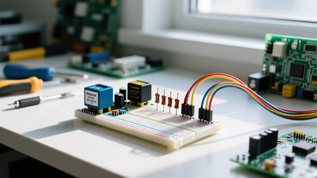
How you physically route power on the breadboard is just as critical as the supply itself. Poor routing introduces ground loops, voltage sag, and high-frequency noise.
Wire Gauge Selection
Standard jumper wire kits use 24 AWG or 22 AWG stranded or solid core wire. While fine for signals, 24 AWG wire has a resistance of roughly 25mΩ per foot. For power injection from your supply to the breadboard rails, use 18 AWG solid core wire with alligator clips or heavy-duty banana-to-pin adapters. This minimizes voltage drop before the power even reaches the breadboard.
Star Grounding vs. Daisy Chaining
Never daisy-chain high-current grounds (like motor drivers or high-power LEDs) through the same breadboard rail used by sensitive analog sensors. The voltage drop across the breadboard's internal metal strips will introduce noise into your sensor readings. Instead, use a star grounding topology: run separate ground wires from the power supply's negative terminal directly to the specific breadboard zones where high-current and low-current components reside.
Mandatory Decoupling
Every active IC on your breadboard requires a decoupling capacitor. Place a 100nF (0.1µF) MLCC ceramic capacitor as physically close to the VCC and GND pins of the IC as possible. Breadboard inductance and power supply cable capacitance can cause high-frequency ringing during IC switching events; the local 100nF capacitor acts as a microscopic, fast-responding local battery to stabilize the voltage rail. For comprehensive prototyping layouts, SparkFun's Breadboard Tutorial offers excellent visual references for capacitor placement.
Troubleshooting Power Delivery Failures
When your circuit behaves erratically, the breadboard and power supply interface is usually the culprit. Use this diagnostic matrix to identify and resolve common prototyping power issues.
| Symptom | Probable Root Cause | Corrective Action |
|---|---|---|
| Microcontroller resets randomly when a motor activates. | Voltage sag on the shared power rail due to high inrush current and breadboard contact resistance. | Separate motor power from logic power. Add a 470µF electrolytic capacitor across the motor's power rails. |
| Jumper wire or breadboard plastic feels warm to the touch. | Exceeding 1A continuous limit on a single contact point or using undersized (24 AWG) wire for power. | Immediately power down. Replace with 18 AWG solid core wire and distribute the current across multiple parallel rails. |
| ADC (Analog-to-Digital) readings are noisy or drifting. | Ground loop or digital noise coupling into the analog ground rail via daisy-chained breadboard strips. | Implement star grounding. Run a dedicated ground wire from the ADC ground pin directly to the power supply ground. |
| Power supply clicks and output drops to zero. | OCP (Over-Current Protection) tripping due to a hidden short circuit or incorrect OCP threshold setting. | Verify circuit for crossed jumper wires. Recalculate expected current draw and adjust the OCP threshold accordingly. |
The Pre-Flight 'Smoke Test' Protocol
Before applying power to a newly assembled breadboard, execute this mandatory three-step protocol to ensure safety:
- Visual Trace: Physically trace the VCC and GND lines with your finger. Ensure no resistor leads or jumper wires are accidentally bridging the power and ground rails.
- Configure Limits: Turn on the bench power supply with the output disabled. Set the target voltage (e.g., 5.0V) and the OCP limit (e.g., 0.5A).
- Monitor and Engage: Connect a digital multimeter (DMM) to the breadboard's furthest power rail. Enable the power supply output. If the DMM reads the target voltage and the supply does not click into CC mode, your circuit is safe to begin operation.
By respecting the mechanical limitations of solderless contacts and leveraging the protective features of modern bench supplies, you can safely prototype complex circuits without risking hardware damage or personal injury. For further reading on component selection and safe wiring practices, consult DigiKey's comprehensive guide to breadboarding.