
The Physics of Failure: Why Safety Protocols Matter
Electronic components checking is a fundamental diagnostic skill, but executing it without strict safety protocols risks both personal injury and catastrophic board-level damage. As semiconductor geometries have shrunk to 3nm and below in 2026, the oxide layers protecting modern ICs are only a few atoms thick. This makes them extraordinarily vulnerable to Electrostatic Discharge (ESD). According to the ESD Association, the Human Body Model (HBM) can generate thousands of volts simply by walking across a synthetic carpet, yet modern MOSFET gates can be permanently punctured by as little as 20V. Furthermore, latent ESD damage—where a component is weakened but not immediately destroyed—can cause intermittent field failures months after the initial bench test.
Workspace Calibration and ESD Mitigation
Before touching a bare PCB, your bench must be calibrated to safely dissipate static charges without creating a short-circuit hazard. A proper ESD-safe workstation relies on a controlled resistance path to ground.
- Dissipative Mats: Use a dual-layer mat like the 3M 8200 series. The top layer should have a surface resistance of $10^6$ to $10^9$ ohms (dissipative), while the bottom layer is conductive ($10^3$ to $10^5$ ohms) to rapidly pull charge to the ground snap.
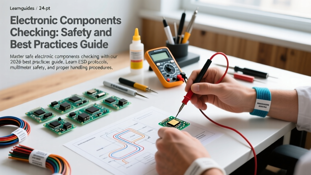
- Wrist Straps: Always wear a wrist strap equipped with a built-in 1-megohm current-limiting resistor, such as the Vermason 231222. This resistor is a critical safety feature; it allows static to bleed off slowly while protecting you from lethal mains shock if you accidentally touch a live 120V/240V trace.
- Ionization: For insulative materials that cannot be grounded (like certain plastic connector housings or conformal coatings), an overhead bench ionizer is mandatory to neutralize localized charge imbalances.
Test Equipment Safety: Avoiding the Ground Loop Trap
The most common cause of bench explosions and destroyed oscilloscopes during electronic components checking is improper grounding of test probes.
Multimeter CAT Ratings
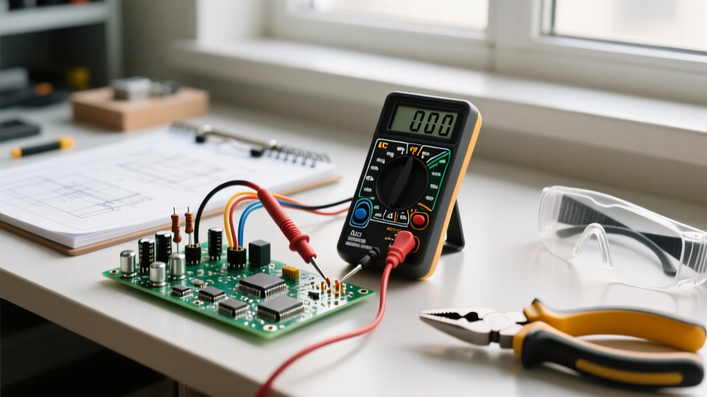
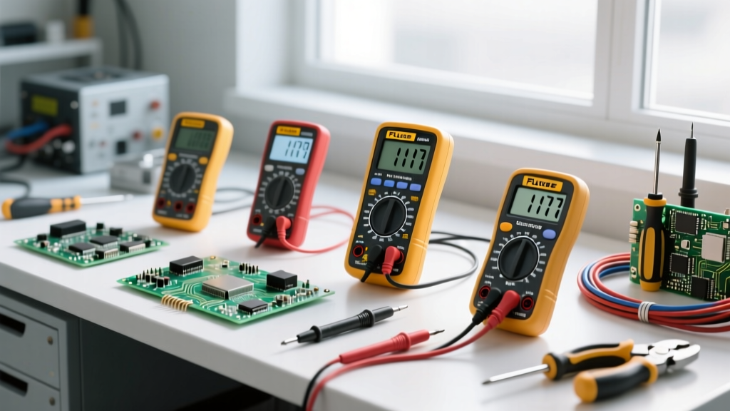
Never use a generic, unrated multimeter for checking components on boards connected to mains power. As detailed in Fluke's multimeter safety guidelines, you must use a meter rated for the environment. For industrial or mains-adjacent PCB troubleshooting, a CAT III 1000V or CAT IV 600V meter (like the Fluke 87V MAX or Keysight U1252B, typically priced between $350 and $500) is required to safely withstand high-energy transient spikes without internal arcing.
The Oscilloscope Ground Lead Danger
Standard passive oscilloscope probes have their ground clips tied directly to the earth ground of the scope's power cord. If you clip the ground lead to a non-grounded node on a live circuit (such as the high-side of a switching MOSFET in an SMPS), you will create a dead short through the scope's internal ground bus, destroying the probe, the scope, and the Device Under Test (DUT). Best Practice: Always use an isolated differential probe (e.g., Tektronix TDP1500, approx. $1,200) when checking floating or high-side components in power electronics.
Component-Specific Checking Matrix & Failure Modes
Different components require distinct testing methodologies to ensure accurate readings and prevent secondary damage from the test equipment itself. Refer to the matrix below for best practices.
| Component Type | Optimal Test Instrument | Safe Checking Procedure | Primary Failure Mode |
|---|---|---|---|
| MLCC Capacitors | ESR Meter / LCR Meter | Discharge fully before testing. Use tweezers to avoid finger capacitance. | Flex-cracking from board bending; short-circuit failure. |
| Power MOSFETs | Digital Multimeter (Diode Mode) | Short Gate-to-Source to discharge before checking Drain-Source body diode. | Gate oxide puncture from ESD; thermal runaway. |
| Schottky Diodes | Multimeter (Diode Mode) | Check forward voltage drop (0.2V - 0.4V). Reverse bias should read OL. | Thermal degradation causing high reverse leakage current. |
| Optocouplers | Source Meter / Curve Tracer | Inject known current into LED; measure phototransistor CTR (Current Transfer Ratio). | LED aging resulting in dropped CTR below operational threshold. |
In-Circuit vs. Out-of-Circuit Verification
Checking components while they are still soldered to the board (in-circuit) is highly susceptible to the "phantom parallel path" problem. If you measure a 10kΩ resistor in-circuit, but it is paralleled by a 10kΩ pull-down network, your meter will read 5kΩ, leading to a false diagnosis of a drifted component.
Best Practice for Out-of-Circuit Checking: When a component must be removed for accurate testing, avoid excessive heat that can delaminate the PCB's internal vias. Use a low-temperature desoldering alloy like Chip Quik (Sn42/Bi58), which melts at 138°C. By mixing this alloy with the existing SAC305 solder, you lower the overall melting point of the joint, allowing safe removal with a standard Hakko FX-888D station set to a safe 220°C, preserving the integrity of the surrounding pads.
Advanced Edge Cases: Dielectric Absorption and Micro-Cracking
Expert-level electronic components checking requires an understanding of edge cases that standard multimeters miss.
Electrolytic Capacitor Dielectric Absorption
When checking older aluminum electrolytic capacitors, a standard capacitance reading might look normal, but the capacitor may suffer from high dielectric absorption (soakage). If a capacitor has been unpowered for years, its internal oxide layer degrades. Applying full rated voltage immediately will cause a massive inrush current and potential venting. Protocol: Always "reform" vintage or long-stored electrolytics using a bench power supply with a strict current limit (e.g., 5mA), slowly stepping up the voltage over several hours while monitoring leakage current.
MLCC Flex Cracks
Multilayer Ceramic Capacitors (MLCCs) are highly brittle. A board that has been mechanically flexed (common in large LED panels or automotive modules) can develop micro-cracks in the MLCC dielectric. These cracks may not show up as a dead short on a multimeter but will cause intermittent leakage under thermal expansion. Inspecting the PCB for bend lines and checking MLCCs along those stress vectors with a thermal camera (like the FLIR C5) under load is a critical diagnostic step.
"Electrical safety is not just about preventing shock; it is about ensuring the integrity of the testing environment to prevent secondary equipment failures and arc flashes during diagnostic procedures." — Adapted from OSHA Electrical Safety Guidelines.
Daily Bench Startup Checklist
To maintain a rigorous safety standard, perform this 3-minute checklist before beginning any electronic components checking:
- Verify Grounding: Test the continuity from your ESD mat snap to the building's known earth ground using a multimeter. Resistance should be less than 1 ohm.
- Inspect Wrist Strap Resistor: Measure the resistance of your wrist strap cord. It must read exactly 1MΩ (±10%). A reading of 0Ω means the safety resistor is blown/bypassed, creating a lethal shock hazard.
- Check Probe Integrity: Inspect oscilloscope and multimeter probe tips for cracked insulation or exposed ground springs. Discard any compromised probes immediately.
- Power Supply Limits: Set your bench power supply's Over-Current Protection (OCP) to a value just above the DUT's expected draw before connecting the board, preventing runaway thermal events if a short exists.
By integrating these safety protocols and precise testing methodologies into your workflow, you protect both yourself and the sensitive electronics you are tasked with diagnosing, ensuring reliable, repeatable results on the bench.