
The Hidden Costs of Untraceable Components in Circuit Design
In the landscape of 2026 circuit design, the global semiconductor supply chain has largely stabilized, yet the secondary market remains a minefield. For hardware engineers and prototyping labs, electronic component traceability is no longer just a compliance requirement for aerospace or medical devices; it is a critical defense mechanism for commercial and DIY projects alike. When you source a microcontroller or a precision analog IC, knowing its exact origin, lot number, and handling history is the only way to guarantee circuit reliability.
The consequences of poor traceability manifest in subtle, catastrophic failure modes. Consider the ubiquitous STM32F103C8T6 microcontroller. While authorized distributors like Mouser or Digi-Key sell genuine STMicroelectronics parts with full lot traceability for around $3.50 to $4.80 per unit, gray-market vendors often offer them for $0.60. These cheap alternatives are frequently "blacktopped"—sanded down and reprinted with laser etching to mimic genuine markings. In practice, these counterfeit ICs may pass basic continuity tests but fail unpredictably when the silicon junction temperature exceeds 70°C, or they may possess only 32KB of flash memory instead of the specified 64KB. Similarly, recycled multilayer ceramic capacitors (MLCCs) harvested from e-waste suffer from degraded dielectrics, leading to severe capacitance drops under DC bias.
According to the SAE AS5553 standard for counterfeit electronic parts, traceability requires an unbroken chain of custody documentation from the original component manufacturer (OCM) to the end user. Without this chain, any component is considered suspect and requires rigorous authentication.
Step-by-Step Traceability Workflow for Prototyping Labs
Implementing a robust traceability protocol does not require a multi-million-dollar facility. By integrating specific inspection and logging steps into your prototyping workflow, you can effectively eliminate gray-market risks.
Phase 1: Procurement and Vendor Qualification
The foundation of electronic component traceability begins at the point of purchase. Always prioritize franchised distributors. If a part is obsolete or on allocation and you must use a broker, verify their status through the Electronic Resellers Association International (ERAI). ERAI maintains a real-time database of reported counterfeit incidents and vetted suppliers. Never procure critical ICs from unverified marketplace vendors without demanding the original Certificate of Conformance (CoC) and the manufacturer's lot code.
Phase 2: Physical Receiving Inspection
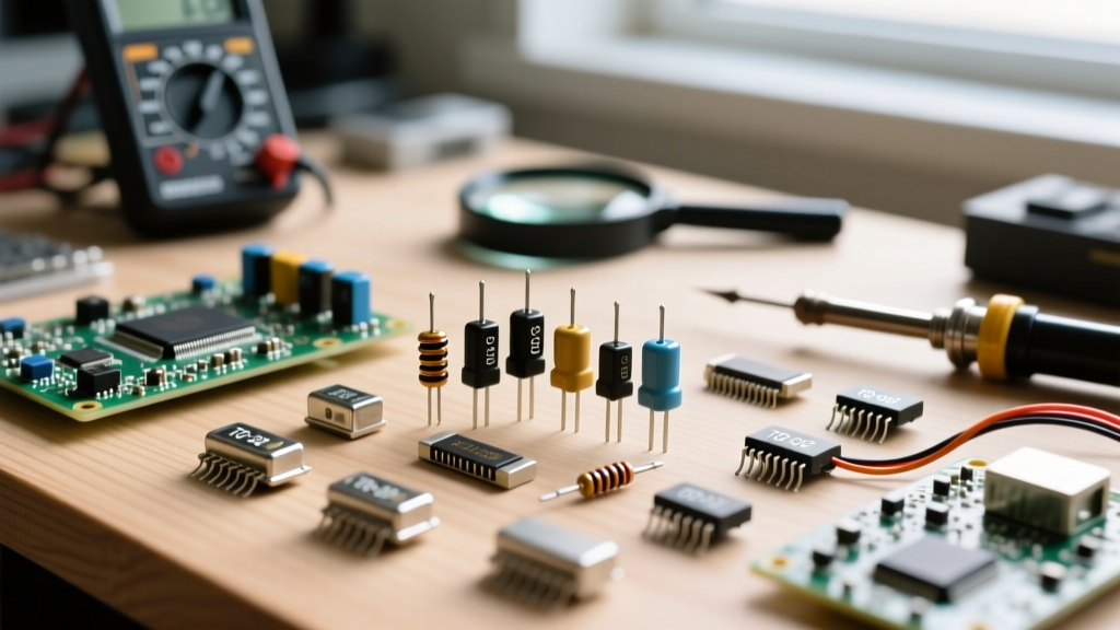
When components arrive, conduct a visual inspection before they enter your inventory. Use a digital microscope with polarized lighting, such as the Dino-Lite AM73915MZT (approximately $850), to examine the IC surface. Polarized light reveals the microscopic swirl marks left by sanding, a dead giveaway of blacktopping. Perform an acetone solvent test: rub the IC marking with an acetone-soaked cotton swab. Genuine laser etching will remain completely unaffected, while counterfeit ink will smear or wipe away entirely. Additionally, verify the pin 1 indicator dimple and check for oxidation on the leads, which indicates the parts were salvaged from old PCBs rather than sourced from fresh tape-and-reel packaging.
Phase 3: Electrical Verification and Destructive Testing
Visual inspection cannot catch "clone" dies that are packaged to mimic the original. For high-stakes prototypes, perform electrical boundary testing. Use a curve tracer to map the I/O pin protection diodes and compare the signature curves against a known golden sample from an authorized distributor. Any deviation in the forward voltage drop or leakage current indicates a different silicon die.
Traceability Verification Matrix
Use the following matrix to determine the appropriate level of traceability verification based on the component's criticality to your circuit design.
| Component Type | Criticality | Required Documentation | Inspection Method | Electrical Test |
|---|---|---|---|---|
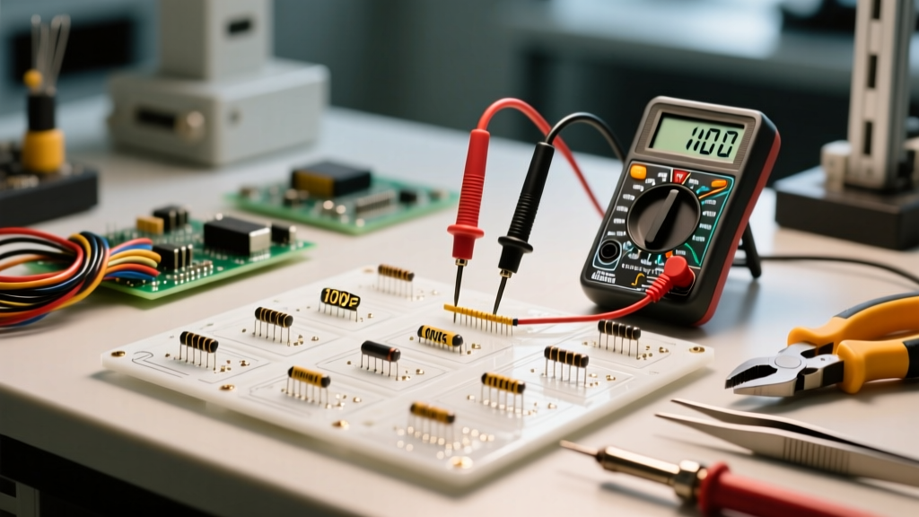
| Passives (R, L, C) | Low to Medium | Packing slip, Lot Code | Visual, Tape/Reel seal check | LCR Meter spot check (10% sample) |
| Standard Logic / Op-Amps | Medium | CoC, Distributor Label | Microscope, Acetone swab test | Curve tracer I/O signature match |
| MCUs / FPGAs / Power ICs | Critical | Full OCM Traceability, CoC | X-Ray, Decapsulation (if suspect) | Boundary scan, functional firmware load |
Practical Application: Catching Fake MLCC Capacitors via DC Bias Testing
One of the most common traceability failures in modern PCB prototyping involves recycled or mislabeled MLCC capacitors. A counterfeit vendor may label a cheap Y5V dielectric capacitor as a high-grade X7R. In a 2026 circuit design, where switching regulators rely on precise output capacitance, this substitution can cause severe voltage ripple and system crashes.
Take the Murata GRM21BR71A106KE51 (10µF, 10V, X7R, 0805) as an example. To verify the dielectric material, you must test the capacitance under a DC bias voltage. Genuine X7R capacitors typically exhibit a capacitance drop of about 30% to 40% when the rated 10V DC bias is applied. Conversely, a fake Y5V capacitor will experience a catastrophic drop, often losing over 80% of its capacitance under the same bias.
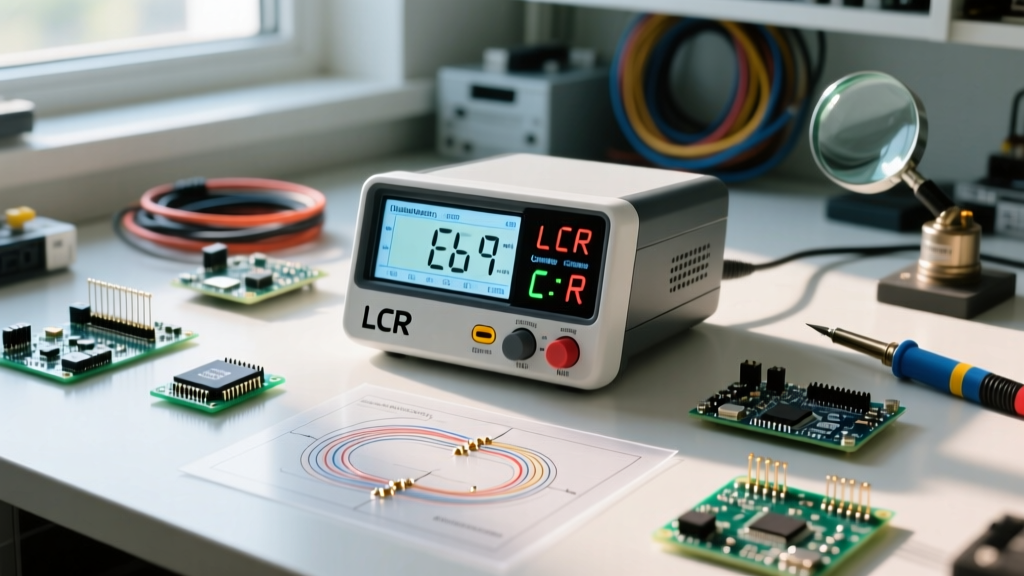
- Solder the suspect 0805 capacitor to a test fixture connected to a bench power supply and an LCR meter (such as the Keysight E4980A or the more budget-friendly DER EE DE-5000).
- Set the LCR meter to measure capacitance at 100kHz with a 1Vrms test signal.
- Gradually increase the DC bias from 0V to 10V.
- Record the capacitance at 10V. If the reading drops below 2µF, reject the entire reel; the dielectric is not X7R, and the traceability documentation is fraudulent.
Integrating 2D Data Matrix Codes into PCB Assembly
Traceability extends beyond the components themselves to the final assembled PCB. For prototyping labs moving toward small-batch production, implementing 2D Data Matrix codes on the board is a best practice. Using a fiber laser marker, etch a unique Data Matrix code onto the PCB silkscreen or directly into the copper solder mask layer.
This code should link to a digital record containing the exact BOM revision, the specific lot numbers of the ICs used on that board, the reflow oven temperature profile, and the date of assembly. If a field failure occurs, scanning the board allows you to instantly trace the failure back to a specific reel of components or a specific batch of solder paste, isolating the root cause without recalling the entire production run. The NASA Electronic Parts and Packaging (NEPP) Program extensively documents how lot-level traceability prevents systemic failures in mission-critical hardware, a principle that scales perfectly down to commercial prototyping.
Software Tools for BOM and Lot Tracking
Managing electronic component traceability via spreadsheets is a recipe for version-control disasters. Modern prototyping labs should utilize dedicated Product Lifecycle Management (PLM) software. InvenTree is a highly recommended open-source inventory management system that allows you to track individual component lots, attach CoC PDFs to specific batch entries, and generate unique barcodes for your storage bins. For enterprise teams, cloud-native platforms like Altium 365 integrate BOM management directly with the schematic capture environment, ensuring that the exact manufacturer part number (MPN) and approved vendor list (AVL) are locked in before the design is sent to fabrication.
Conclusion
Electronic component traceability is an active, ongoing process that bridges the gap between schematic theory and physical reliability. By qualifying vendors through ERAI, performing targeted physical and electrical inspections, and utilizing DC bias testing for passives, you fortify your prototyping lab against the persistent threats of the gray market. Treat every component lot as a critical variable in your circuit's success, and your designs will perform reliably long after they leave the bench.