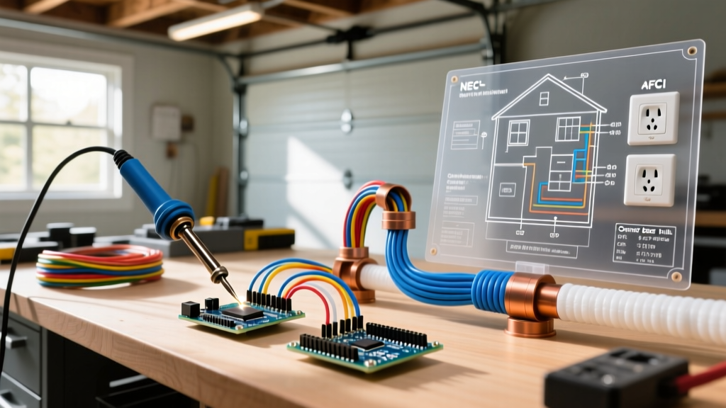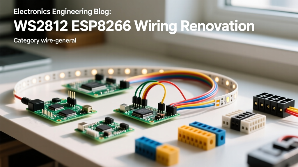

When executing a whole-home smart lighting renovation, the decision to integrate addressable LEDs must happen long before the drywall goes up. Unlike standard 120V AC recessed lighting, low-voltage digital LED systems require meticulous planning regarding voltage drop, data signal degradation, and microcontroller placement. Mastering the ws2812 led strip to esp8266 wiring topology requires understanding both DC power distribution and digital signal integrity. This guide outlines the architectural blueprint for pre-wiring addressable lighting during a home remodel, ensuring your smart home infrastructure is robust, code-compliant, and flicker-free.
Pre-Rough-In: Sizing the 5V Power Infrastructure
The most common failure point in custom LED renovations is undersizing the power supply and attempting to push 60 amps of current through 22-gauge ribbon cables. WS2812B LEDs draw approximately 60mA per chip at maximum brightness (full white). A standard 5-meter strip with 60 LEDs per meter contains 300 LEDs, demanding up to 18 Amps at 5V.
During the rough-in phase, you must install dedicated low-voltage junction boxes near your planned LED zones to house industrial-grade switching power supplies. The Mean Well LRS-300-5 (5V, 60A) is the gold standard for these installations. It provides clean, regulated DC power and features built-in overload and short-circuit protection.
Power Injection Strategy
You cannot power a long run of WS2812B LEDs from a single end. The copper traces on standard flexible printed circuit boards (FPCBs) are too thin to carry high amperage over long distances, leading to severe voltage drop. This manifests as a color shift—where the end of the strip glows yellow or red instead of white—and eventual data corruption.
- The 150-LED Rule: Inject 5V power at least every 150 LEDs (approximately 2.5 meters on high-density strips).
- Bidirectional Injection: For runs up to 5 meters, inject power from both the beginning and the end of the strip.
- Capacitor Buffering: Install a 1000µF, 10V (or higher) electrolytic capacitor across the 5V and GND terminals at the power injection point to smooth out transient voltage spikes during high-demand color transitions.
Wire Gauge Selection for In-Wall Runs
When routing power through walls to accessible attic or basement junction boxes, use stranded copper wire. Solid core wire is prone to breaking under the thermal expansion and vibration typical in residential structures.
| Run Length (One Way) | Recommended Power Wire (5V) | Max Current Capacity | Voltage Drop Estimate |
|---|---|---|---|
| Up to 2 Meters | 18 AWG Stranded | 16 Amps | < 0.05V (Negligible) |
| 2 to 5 Meters | 16 AWG Stranded | 22 Amps | < 0.10V (Acceptable) |
| 5 to 10 Meters | 14 AWG Stranded | 32 Amps | < 0.15V (Requires Injection) |
| 10+ Meters | 12 AWG Stranded | 40 Amps | Move PSU closer to load |
The ESP8266 Hub: Logic Shifting and GPIO Selection
The ESP8266 (commonly deployed via the NodeMCU or D1 Mini form factor) is the brain of the operation, typically running the open-source WLED firmware. However, integrating this 3.3V microcontroller with a 5V WS2812B data line introduces a critical logic level mismatch.
Solving the 3.3V to 5V Logic Mismatch
The WS2812B protocol requires a data signal high voltage (V-IH) of at least 0.7 x VDD. With a 5V power supply, the strip expects a minimum of 3.5V to reliably register a logic '1'. The ESP8266 only outputs 3.3V. While some LED batches will tolerate 3.3V, in a permanent home renovation, relying on marginal voltage tolerances is a recipe for intermittent flickering and ghosting.
Renovation Pro-Tip: Always install a 74AHCT125 logic level shifter between the ESP8266 and the WS2812B data line. Power the 74AHCT125 with 5V, feed the 3.3V ESP8266 signal into the input, and the chip will output a rock-solid 5V data signal. This single component eliminates 90% of unexplained data corruption issues in smart home builds.
ESP8266 Boot Strapping and Pin Selection
Not all GPIO pins on the ESP8266 are created equal. The microcontroller uses specific pins to determine its boot mode. If you wire your LED data line or a relay to the wrong pin, your smart home hub will fail to boot after a power outage.
- GPIO 2 (D4): The optimal pin for WS2812 data output. It is high at boot, which is safe for WLED initialization.
- GPIO 0 (D3): Must be HIGH at boot. Avoid using this for LED data, as the strip's initial power surge could pull the pin low, forcing the ESP into flash programming mode.
- GPIO 15 (D8): Must be LOW at boot. Never connect this to a 5V LED data line or a relay module with a pull-up resistor.
In-Wall Routing and NEC Code Compliance
Running low-voltage DC wiring inside residential walls requires adherence to the National Electrical Code (NEC), specifically NEC Article 725 regarding Class 1 and Class 2 remote-control and signaling circuits.
Separation from Mains Voltage
Your 5V DC power and data lines must never share the same conduit, junction box, or drill hole as 120V/240V AC mains wiring. If a low-voltage wire must cross a high-voltage wire, they must do so at a strict 90-degree angle. If parallel runs are unavoidable, maintain a minimum separation of 1/4 inch, or use a continuous, firmly fixed non-conductive barrier (such as a flexible ENT 'smurf tube' conduit) to isolate the low-voltage harness.
Accessible Junction Strategies
Do not bury soldered connections inside walls. Solder joints can become brittle over time due to structural settling and thermal cycling. Instead, route your 14 AWG or 16 AWG in-wall power feeds into accessible, blank-faced junction boxes. Inside these boxes, use Wago 221 Series Lever-Nuts to transition from the thick in-wall wire to the 20 AWG silicone pigtails attached to your LED strips. Wago connectors are rated for 32A, provide a gas-tight connection, and allow for future maintenance without stripping wires or applying heat.
Data Signal Integrity Over Long Runs
While power injection solves voltage drop, the digital data signal degrades over distance and is highly susceptible to electromagnetic interference (EMI) from nearby AC lines or Wi-Fi routers.
The 470Ω Resistor Rule
Always place a 300Ω to 500Ω (470Ω is standard) carbon film resistor on the data line, as close to the first LED's DIN pad as possible. This resistor prevents high-frequency signal reflections and protects the first LED's internal microcontroller from voltage spikes if the data line is connected while power is absent. In a renovation, where wires are pulled through studs and terminated later, this resistor acts as a vital shock absorber for the data line.
The Sacrificial First LED Trick
If your ESP8266 hub is located in a basement and the data line must travel 15 feet through walls to reach the living room ceiling cove, the raw data signal will likely degrade before reaching the strip. To solve this, wire a single, standalone WS2812B LED (or a short 3-LED segment) near the ESP8266 hub. Connect the long in-wall data cable to the DOUT pad of this sacrificial LED. The LED acts as a signal repeater, buffering and regenerating the 5V square wave before it travels through the long cable run. Set this single LED to 'off' or hide it inside the junction box, and configure your WLED software to start the active strip at LED index 1.
Final Rough-In Inspection Checklist
Before the insulation and drywall crews arrive, verify your low-voltage infrastructure:
- Verify all Mean Well power supplies are mounted in ventilated, accessible enclosures.
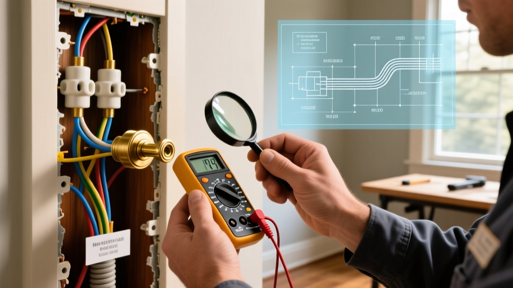
- Test continuity on all in-wall 14/16 AWG power feeds using a multimeter.
- Confirm logic level shifters are installed and receiving 5V VCC.
- Ensure the 470Ω data resistor is installed at the termination point.
- Validate that no 5V DC wires share physical space with 120V AC Romex.
By treating your ws2812 led strip to esp8266 wiring as a permanent architectural system rather than a temporary hobby project, you guarantee a smart home lighting installation that is stable, safe, and ready for decades of operation.