
Beyond the Knob: Understanding the Electric Potentiometer
While often dismissed as a simple volume control, the electric potentiometer is a highly versatile three-terminal electromechanical transducer. In prototyping and circuit design, it serves two distinct electrical functions: a variable voltage divider and a rheostat (variable resistor). Misunderstanding these configurations—or ignoring the physical limitations of the resistive track—leads to noisy ADC readings, erratic microcontroller behavior, and premature component failure.
This tutorial dives deep into the practical application of electric potentiometers, covering taper selection, microcontroller interfacing, source impedance matching, and failure-mode mitigation.
Decoding Tapers and Markings
Before wiring any circuit, you must identify the potentiometer's taper (the relationship between shaft rotation and resistance ratio). The industry standard marking system uses letters to denote the curve, though regional variations exist. In the Asian and modern European standard (which dominates component suppliers like Mouser and Digi-Key), the letter precedes the value.
| Marking | Taper Type | Curve Behavior | Primary Application |
|---|---|---|---|
| B10K | Linear | Resistance changes at a constant rate relative to rotation. | Position sensors, LED dimming, microcontroller ADC inputs. |
| A10K | Logarithmic (Audio) | Slow initial change, rapid change near the end of rotation. | Audio volume controls (matches human ear's logarithmic loudness perception). |
| C10K | Anti-Log (Reverse Audio) | Rapid initial change, slow change near the end. | Specialized tone controls, specific op-amp feedback networks. |
Note: Older US-standard components may use 'A' for Linear and 'C' for Logarithmic. Always verify with a multimeter by measuring the wiper-to-ground resistance at the 50% rotation mark. A linear pot will read exactly 50% of its total resistance; an audio pot will read roughly 10% to 20%.
Application 1: The Voltage Divider (Microcontroller Interfacing)
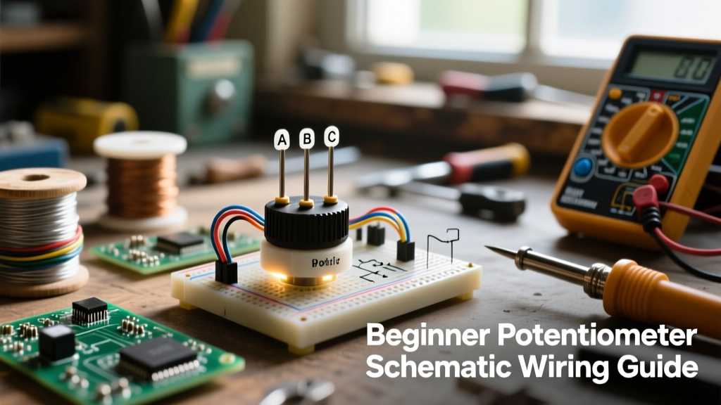
The most common use of an electric potentiometer in modern DIY electronics is as a voltage divider to feed an analog-to-digital converter (ADC), such as the 10-bit ADC on an ATmega328P (Arduino Uno). To wire this, Terminal 1 connects to VCC (e.g., 5V), Terminal 3 connects to GND, and the Wiper (Terminal 2) connects to the microcontroller's analog input pin.
The Source Impedance Trap
A critical mistake prototypers make is selecting a 100kΩ or 500kΩ potentiometer to 'save power.' According to the official Arduino analog read documentation, the ADC relies on an internal sample-and-hold (S&H) capacitor (typically around 14pF). This capacitor must charge to the input voltage level within a fraction of a microsecond during the sampling phase.
If your potentiometer's Thevenin equivalent resistance (source impedance) is too high, the S&H capacitor cannot fully charge, resulting in erratic, jittery ADC readings. For standard 10-bit AVR ADCs, the source impedance should be 10kΩ or less. Therefore, a 10kΩ linear (B10K) electric potentiometer is the optimal choice, balancing low power consumption with reliable ADC charging.
Mitigating Wiper Noise with an RC Filter
Mechanical wipers bouncing across a carbon track generate high-frequency electrical noise. To clean the signal before it reaches the microcontroller, implement a passive low-pass RC filter directly at the wiper terminal. Soldering a 100nF (0.1µF) ceramic capacitor between the wiper and ground creates a filter. Combined with a 10kΩ pot's maximum Thevenin resistance of 2.5kΩ (at the 50% mark), the cutoff frequency is approximately 636Hz, effectively eliminating contact bounce noise without sacrificing dial responsiveness.
Application 2: The Rheostat (Variable Resistor)
When you need to vary current or alter an op-amp's feedback loop, you use the potentiometer as a two-terminal rheostat. This is done by connecting the circuit to Terminal 1 and the Wiper (Terminal 2), leaving Terminal 3 floating.
Crucial Reliability Rule: Never leave the third terminal floating. Always short the unused terminal to the wiper. If the wiper lifts off the resistive track due to vibration, oxidation, or mechanical shock, a floating terminal results in an open circuit (infinite resistance). In an LED driver circuit, this could cause a current spike that destroys the diode. By tying the wiper to the unused terminal, a wiper failure simply defaults the component to its maximum rated resistance, keeping the circuit safe.
Material Science: Carbon vs. Cermet vs. Conductive Plastic
Not all electric potentiometers are built for the same environment. The resistive element's material dictates the component's lifespan, noise floor, and use case. Consult the Bourns Potentiometer catalog for deep-dive material specifications, but here is the practical prototyping breakdown:
- Carbon Composition: The standard for cheap panel-mount pots. Prone to Contact Resistance Variation (CRV) and wiper noise as the carbon wears down. Rated for ~15,000 rotation cycles.
- Cermet (Ceramic-Metal): Used almost exclusively in PCB-mount trimmer pots (like the iconic Bourns 3296W). Highly stable across temperature extremes and capable of precise micro-adjustments. However, cermet is brittle and degrades rapidly if used as a daily user interface. Rated for ~200 adjustment cycles.
- Conductive Plastic: The gold standard for high-end audio and precision robotics (e.g., TT Electronics P260 series). Offers near-infinite resolution, ultra-low CRV (<1 ohm), and lifespans exceeding 1,000,000 cycles. Expensive, but necessary for precision PID controller feedback loops.
Troubleshooting Common Prototyping Failures
1. 'Jumpy' Analog Readings
Cause: High source impedance or missing bypass capacitor.
Fix: Drop to a 10kΩ pot and add a 100nF capacitor from the wiper to GND. Additionally, ensure your microcontroller's VCC is stable; a fluctuating 5V rail will inherently cause the voltage divider output to fluctuate.
2. Non-Linear Dimming on LEDs
Cause: Human eyes perceive light logarithmically, but a linear (B) pot outputs voltage linearly. The LED will appear to jump from 'off' to 'blinding' in the first 20% of the rotation.
Fix: Either switch to an anti-log (C) taper potentiometer, or maintain the linear pot and implement a software gamma-correction lookup table in your microcontroller's firmware to map the linear ADC input to a logarithmic PWM output.
3. Scratchy Audio Output
Cause: Dust accumulation or oxidized carbon tracks inside an aging audio taper pot.
Fix: Inject a small amount of specialized contact cleaner (like DeoxIT D5) into the casing slot while rotating the shaft. Do not use standard WD-40, as it leaves a dielectric residue that will permanently ruin the conductive carbon path.
Summary
Mastering the electric potentiometer requires looking past the physical dial and understanding the electrical realities of the wiper, the taper curve, and the source impedance. By selecting the correct material (cermet for trimming, conductive plastic for precision, carbon for general purpose), wiring voltage dividers with ADC limitations in mind, and always protecting rheostat configurations against open-circuit failures, you elevate your prototypes from fragile experiments to robust, production-ready designs. For further reading on fundamental resistor networks, review the voltage divider tutorials at Electronics Tutorials.