
Decoding the Potentiometer Schematic Symbol
When you first unbox an electronics starter kit, you will inevitably find a small bag of three-terminal dials. These are potentiometers, and while physically simple, their representation on a potentiometer schematic can confuse beginners. To master circuit design, you must understand how these symbols translate to physical copper tracks and wiper arms.
In standard IEEE/US schematics, a potentiometer is drawn as a zigzag resistor line with an arrow pointing directly at the center. In IEC/European schematics, it appears as a rectangular box with an arrow intersecting it. In both cases, the line represents the fixed resistive element (the track), and the arrow represents the wiper—the movable contact that slides along the track to divide the resistance.
Pro Tip: If the arrow on the schematic crosses completely through the resistor line and terminates on the other side, it usually denotes a rheostat (variable resistor) configuration where only two pins are actively used in the circuit path.
The Anatomy of Your Kit's Trimpot and Panel Mount
Most beginner kits include two distinct types of potentiometers, and knowing their physical limitations is crucial for reading and designing schematics accurately.
Bourns 3386P vs. Alpha 9mm: What's in the Bag?
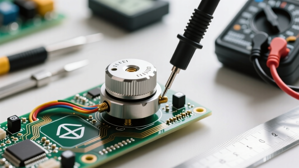
- The Blue Square Trimpot (Bourns 3386P style): These are cermet (ceramic/metal) potentiometers designed for PCB mounting. They typically handle up to 0.5W of power and are meant for occasional calibration (e.g., tuning a sensor threshold). They require a small flathead screwdriver to adjust.
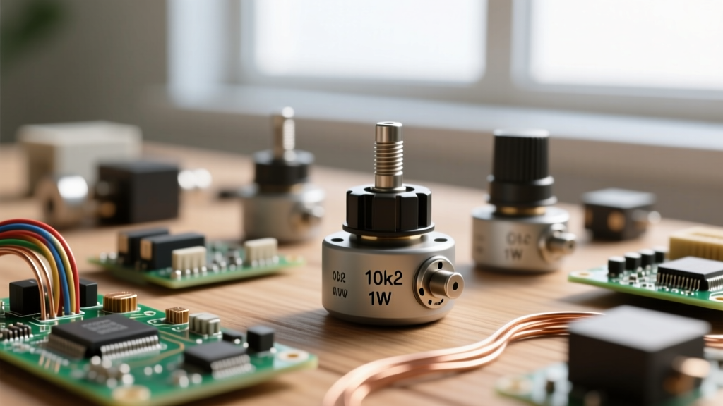
- The Panel Mount Pot (Alpha RD901F style): These feature a metal or plastic shaft meant for a knob. They use a carbon composition track, usually rated for much lower power (around 0.05W to 0.1W). They are designed for continuous user interaction, like volume control or LED dimming.
According to the Bourns 3386P datasheet, the cermet track offers superior stability over temperature changes compared to carbon, making trimpots ideal for precision voltage dividers in your schematic designs.
Taper Types: Reading the Silkscreen and Schematic Notes
A critical detail often missed in basic schematics is the taper—the rate at which resistance changes relative to the shaft rotation. While the schematic symbol remains the same, a well-drawn schematic will include a note specifying the taper.
| Taper Type | Kit Marking | Schematic Note | Best Application |
|---|---|---|---|
| Linear | B10K | Lin or Linear | LED dimming, Arduino analog inputs, voltage division |
| Audio (Logarithmic) | A10K | Log or Audio | Audio volume control (matches human hearing perception) |
| Anti-Log | C10K | Anti-Log | Specialized audio balancing and vintage synth circuits |
If your schematic calls for an analog sensor reading on a microcontroller, always ensure you are sourcing a B-taper (Linear) potentiometer from your kit. Using an A-taper will result in highly non-linear, unpredictable data mappings.
Wiring the Three Pins: Voltage Divider vs. Variable Resistor
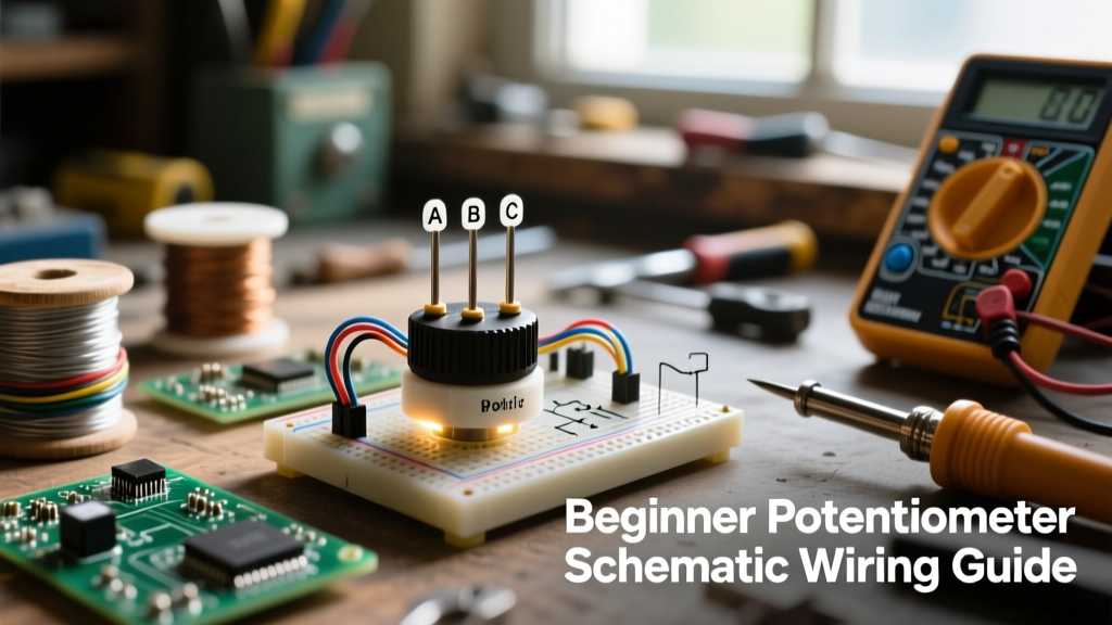
The physical component has three pins: Pin 1 (Counter-Clockwise), Pin 2 (Wiper), and Pin 3 (Clockwise). How you wire these pins fundamentally changes the circuit's behavior and its corresponding schematic representation.
Mode 1: The Voltage Divider (All 3 Pins Used)
This is the most common configuration in microcontroller projects. Pin 1 connects to Ground (GND), Pin 3 connects to VCC (e.g., 5V), and Pin 2 (the wiper) outputs a variable voltage between 0V and 5V. The SparkFun Voltage Divider tutorial perfectly illustrates the math governing this: V(out) = V(in) × (R2 / (R1 + R2)). On the schematic, you will see the VCC and GND nets attached to the ends of the resistor symbol, with the wiper arrow routing to an ADC pin or op-amp input.
Mode 2: The Rheostat (Only 2 Pins Used)
If your schematic shows the wiper arrow tied directly to one of the end terminals, the potentiometer is acting as a two-terminal variable resistor. This is used to control current flow directly, such as setting the gain on an operational amplifier or limiting current to an LED. Warning: Never wire a low-resistance potentiometer (e.g., 100Ω) directly across a 5V power supply as a rheostat; the current will exceed the component's wattage rating and burn the carbon track.
Common Beginner Mistakes and Schematic Troubleshooting
Even if you copy a potentiometer schematic perfectly, physical realities can cause circuit failure. Watch out for these specific failure modes:
- Floating Wiper Noise: If the schematic does not include a pull-down or pull-up resistor, and the wiper loses physical contact with the track due to dust or wear, the output pin will "float." This causes wild voltage spikes. Always design your microcontroller firmware to handle sudden 1023-to-0 ADC jumps.
- Wiper Contact Resistance: Cheap carbon pots from beginner kits can have a wiper contact resistance of up to 100 ohms. In high-impedance circuits, this is negligible. In low-impedance precision circuits, this introduces significant error.
- Mechanical Stress on PCB Traces: When soldering panel-mount pots to a custom PCB, the physical force of turning the knob can rip the copper pads right off the board. Schematics don't show this, but good PCB layout dictates using mechanical mounting brackets, not just the three solder joints, to bear the physical load.
Real-World Arduino Integration: Reading the Wiper
Let's translate the potentiometer schematic into physical code. When wiring the wiper to an Arduino Uno's A0 pin, you are utilizing the ATmega328P's internal 10-bit Analog-to-Digital Converter (ADC). As detailed in the Arduino analogRead() documentation, this maps the 0-5V range to integer values between 0 and 1023.
However, beginners often encounter "ADC jitter," where the serial monitor displays fluctuating values (e.g., 512, 515, 509) even when the knob is completely still. This is caused by electromagnetic interference and the high output impedance of the potentiometer's wiper.
The Hardware Fix: Add a 0.1µF (100nF) ceramic capacitor between the wiper pin (Pin 2) and Ground. This creates a low-pass RC filter, smoothing out high-frequency noise and providing a rock-solid, stable voltage to the microcontroller's sample-and-hold circuit. This simple addition bridges the gap between a theoretical potentiometer schematic and a robust, production-ready prototype.
Summary: From Symbol to Solder
Mastering the potentiometer schematic requires more than just memorizing a symbol with an arrow. It demands an understanding of taper, power dissipation limits, and the physical realities of carbon versus cermet tracks. By recognizing whether your circuit demands a voltage divider or a rheostat, and by implementing hardware filtering for microcontroller integration, you elevate your prototyping skills from beginner to intermediate. Next time you reach into your component kit for that blue Bourns trimpot or Alpha panel dial, you will know exactly how to design, wire, and troubleshoot it for optimal performance.