
The Physics of Ultrasonic Distance Measurement
When robotics engineers and DIY makers discuss sonar sensor range, they are usually referring to ultrasonic time-of-flight (ToF) measurement. Unlike infrared or LiDAR, which rely on electromagnetic waves, ultrasonic sensors utilize mechanical sound waves—typically at a frequency of 40kHz, which is well above human hearing. At 20°C in dry air, sound travels at approximately 343 meters per second. The microcontroller sends a trigger pulse, the piezoelectric transducer emits an acoustic burst, and the system measures the time it takes for the echo to return.
However, maximizing your effective sonar sensor range is rarely as simple as reading the maximum distance printed on the box. Acoustic waves are subject to the inverse square law, atmospheric attenuation, and complex reflection geometries. A sensor rated for 5 meters in a controlled anechoic chamber may struggle to detect a cardboard box at 2 meters in a noisy warehouse. In this equipment roundup, we dissect the hardware, physics, and environmental variables that dictate real-world ultrasonic performance.
Blind Spots and Beam Angles: Why Range Isn't Everything
Before comparing specific kits, it is critical to understand the acoustic dead zone. Every ultrasonic transducer suffers from a minimum range limitation, commonly known as the blind spot.
Transducer Ringing and the Acoustic Dead Zone
When the electrical pulse ends, the piezoelectric crystal does not stop vibrating instantly. It continues to 'ring' or resonate for a few hundred microseconds. If an object is too close, the returning echo overlaps with this residual ringing, making it impossible for the receiver circuitry to distinguish the echo from the initial transmission. For standard 40kHz open-mesh transducers, this blind spot is typically between 2cm and 20cm, depending on the damping circuitry of the specific kit.
Furthermore, sound behaves like a flashlight beam rather than a laser pointer. According to MaxBotix's guide on ultrasonic beam patterns, a standard 40kHz transducer in open air has a beam angle of roughly 15 to 30 degrees. As the target moves further away, the acoustic footprint expands, increasing the likelihood of detecting unwanted background objects (clutter) and reducing the acoustic energy density that reflects back to the sensor.
Equipment Roundup: Comparing Sonar Sensor Range by Kit
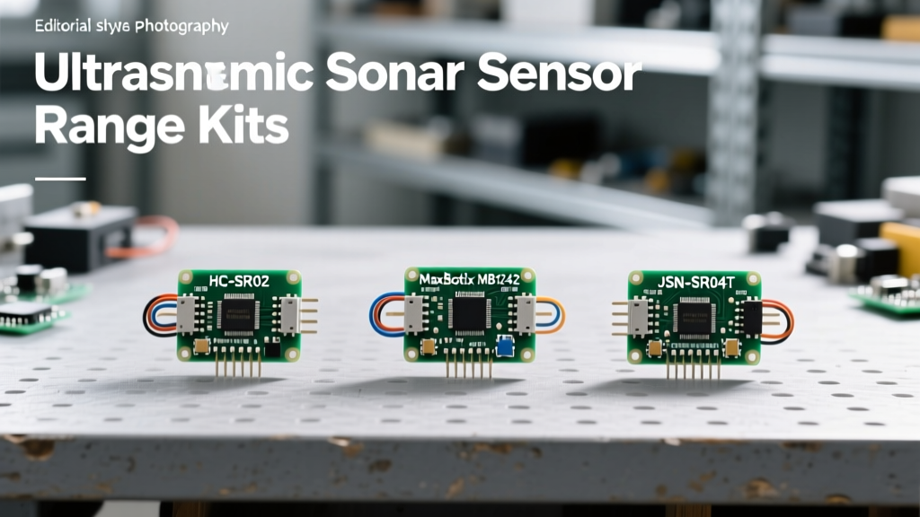
To help you select the right hardware for your next rover, drone, or liquid-level monitor, we have rounded up three distinct classes of ultrasonic kits. Below is a comparative breakdown of their core specifications.
| Model / Kit | Frequency | Max Range | Blind Spot | Beam Angle | Interface | Avg. Price |
|---|---|---|---|---|---|---|
| HC-SR04 | 40 kHz | 400 cm | ~2 cm | ~15° | Digital Pulse | $2.00 |
| JSN-SR04T (V2.0) | 40 kHz | 450 cm | ~20 cm | ~25° | Digital Pulse | $6.50 |
| MaxBotix MB7389 | 42 kHz | 500 cm | ~30 cm | ~12° (Focused) | Analog/PWM/RS232 | $115.00 |
HC-SR04: The Baseline Hobbyist Standard
The HC-SR04 is the undisputed king of entry-level robotics. Its sonar sensor range is theoretically 4 meters, though reliable readings on non-ideal surfaces (like fabric or angled wood) usually drop off around 2.5 meters. The onboard LM324 comparator and ST232A chip handle the analog-to-digital conversion, outputting a simple high/low pulse on the Echo pin. Its primary limitation is poor shielding and high susceptibility to acoustic crosstalk when multiple sensors are deployed on a single chassis.
JSN-SR04T: The Rugged Outdoor Alternative
If your project involves outdoor navigation or liquid tank monitoring, the JSN-SR04T is the necessary upgrade. By separating the transducer from the PCB via a 2.5-meter shielded cable, the acoustic element can be mounted flush against a waterproof enclosure. The trade-off for its rugged, sealed transducer design is a significantly larger blind spot (often 20cm to 25cm) due to the heavy damping required to prevent the waterproof membrane from ringing excessively.
MaxBotix MB7389: The Industrial Heavyweight
For professional AGVs (Automated Guided Vehicles) and precision industrial vats, the MaxBotix HR-MaxSonar-WR series is the gold standard. As detailed in Texas Instruments application notes on acoustic time-of-flight, industrial sensors require advanced signal processing to filter out ambient acoustic noise. The MB7389 features a tightly focused beam, IP67 weather resistance, and real-time temperature compensation, ensuring that its 5-meter sonar sensor range remains accurate regardless of environmental shifts.
Real-World Failure Modes and Environmental Interference
Hardware is only half the battle. The environment in which you deploy your ultrasonic kit will drastically alter its effective range and reliability.
Temperature Drift and the Speed of Sound
The speed of sound is not a constant; it is highly dependent on ambient temperature. The formula for the speed of sound in dry air is v = 331.3 + (0.606 × T), where T is the temperature in Celsius. If your microcontroller assumes a static speed of 343 m/s (calibrated for 20°C), but your rover is operating outdoors at 0°C, the actual speed of sound drops to 331.3 m/s. Over a 4-meter round trip, this temperature differential introduces a ranging error of nearly 14 centimeters. High-end kits like the MaxBotix include an onboard thermistor to dynamically adjust the ToF calculation, while HC-SR04 users must wire an external DS18B20 temperature sensor and apply the math in software.
Specular Reflections and Target Geometry
Ultrasonic waves behave much like light when hitting smooth, hard surfaces. If a robot approaches a flat wall at a 45-degree angle, the acoustic wave will reflect away from the sensor (specular reflection) rather than bouncing back. The sensor will read a 'timeout' or maximum range, falsely indicating a clear path. To mitigate this, roboticists often mount sensors at slight downward or outward angles, or rely on sensor fusion with infrared ToF sensors to catch angled drop-offs.
Wiring and Code Optimization for Maximum Range
When pushing a sensor to its maximum rated distance, signal degradation on the PCB traces and jumper wires becomes a major factor. The Echo pin on an HC-SR04 is essentially a high-impedance digital output. If you run a wire longer than 30cm from the sensor to your Arduino or Raspberry Pi, parasitic capacitance can cause the voltage rise time to slow down, resulting in missed interrupts or erratic microsecond timings.
Expert Wiring Tip: If you must extend the signal wires of an ultrasonic sensor to reach your microcontroller, do not rely on the raw Echo pin. Instead, place a 74HC14 Schmitt Trigger buffer or a simple NPN transistor near the sensor to square off the signal before it travels down the cable. Additionally, ensure your trigger pulse is exactly 10µs; longer pulses can cause internal timing overlaps in cheaper clone boards, artificially capping your maximum readable range.
Furthermore, if you are building an array of three or more sonar sensors to achieve 360-degree coverage, you must manage acoustic crosstalk. Firing all sensors simultaneously will cause them to detect each other's echoes. The most reliable solution is Time-Division Multiplexing (TDM): fire Sensor A, wait for the echo (or a 30ms timeout), then fire Sensor B. While this reduces the overall refresh rate of your array, it guarantees the integrity of the sonar sensor range data.
Final Verdict: Choosing the Right Kit for Your Project
Optimizing your sonar sensor range requires matching the hardware to the physical realities of your operating environment. For indoor, short-range obstacle avoidance on a budget, the HC-SR04 remains perfectly adequate, provided you account for its narrow blind spot and temperature sensitivity. For outdoor rovers, wet environments, or liquid level sensing, the JSN-SR04T offers necessary physical isolation and durability, albeit with a larger acoustic dead zone. Finally, for mission-critical navigation, high-speed robotics, or environments requiring precise beam targeting, the investment in a MaxBotix MB7389 pays for itself through superior signal processing, multi-interface outputs, and uncompromising range reliability.