
Why Your First Wireless Project Might Fail
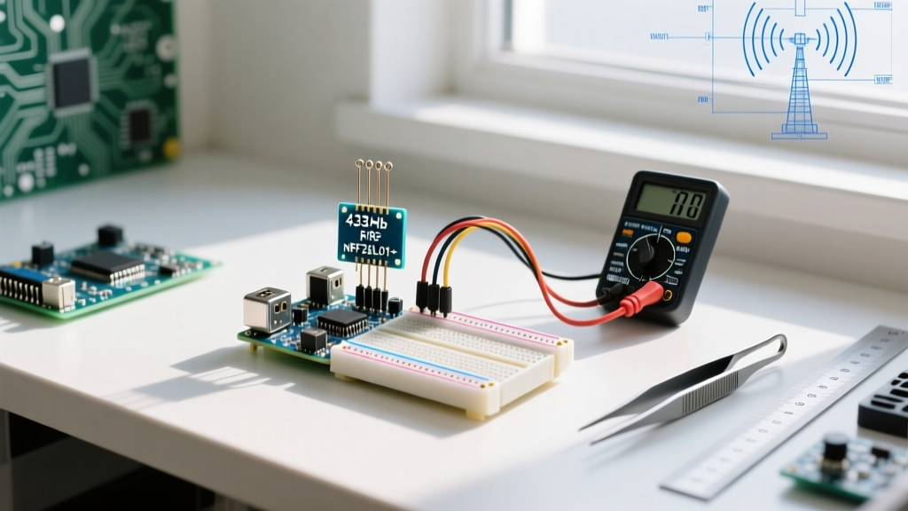
Adding wireless communication to an Arduino or Raspberry Pi project feels like magic until your first RF module test returns nothing but silence. Unlike wired protocols like I2C or UART, radio frequency (RF) communication is invisible and heavily influenced by physics, power supply noise, and environmental interference. In this beginner tutorial, we will demystify the two most popular entry-level wireless components: the ultra-cheap 433MHz ASK (Amplitude Shift Keying) transmitters and the highly reliable 2.4GHz nRF24L01+ transceivers. By the end of this guide, you will understand exactly how to calculate antenna lengths, decouple power rails, and troubleshoot silent SPI links.
The Big Three: ASK, 2.4GHz, and LoRa
The hardware market is flooded with generic RF modules, but they generally fall into three distinct architectures for beginners. Understanding the difference will save you hours of frustration when selecting a module for your specific DIY scenario.
| Module Type | Frequency | Protocol | Avg. Cost | Best Use Case |
|---|---|---|---|---|
| MX-FS-03V / MX-05V | 433MHz / 315MHz | ASK / OOK | $1 - $2 | Simple remote controls, garage doors, weather sensors |
| nRF24L01+ | 2.4GHz | GFSK (Packet) | $3 - $6 | Bi-directional data, RC cars, wireless telemetry |
| SX1278 (LoRa) | 433MHz / 868MHz | Chirp Spread Spectrum | $8 - $12 | Long-range (km) low-power IoT, agriculture, GPS tracking |
The 433MHz ASK modules are essentially 'dumb' radios. If you feed a logic HIGH to the transmitter's DATA pin, it broadcasts RF energy. If you feed a LOW, it stops. The receiver (usually a super-regenerative design like the MX-05V) constantly amplifies ambient noise until it detects a strong carrier signal. This means you must use a software encoding library to send packets, otherwise, the receiver will just output random static to your microcontroller's interrupt pins.
Conversely, the nRF24L01+ is a smart transceiver. It handles packetization, error checking (CRC), and automatic re-transmission via the SPI bus. You don't worry about the raw RF wave; you simply pass byte arrays to the module's internal registers.
The Physics of the Wire: Antenna Tuning
The most common mistake beginners make with an RF module is ignoring the antenna. Wrapping a random piece of copper wire around a pencil and soldering it to the ANT pad will result in terrible range and high signal reflection (VSWR), which can even damage the transmitter's final amplifier stage over time.
Calculating the Perfect Quarter-Wave Antenna
For a simple monopole wire antenna, you want to cut it to exactly one-quarter of the signal's wavelength ($\lambda/4$). The formula is:
Length (meters) = Speed of Light (300,000,000 m/s) / (4 * Frequency in Hz)
- For 433MHz: 300,000,000 / (4 * 433,000,000) = 0.173 meters, or 17.3 cm.
- For 315MHz: 300,000,000 / (4 * 315,000,000) = 0.238 meters, or 23.8 cm.
- For 2.4GHz (nRF24L01+): 300,000,000 / (4 * 2,400,000,000) = 0.031 meters, or 3.1 cm.
Note: Always keep your 2.4GHz antenna straight. Coiling a 2.4GHz wire creates an inductor that shifts the resonant frequency entirely out of band, effectively killing your range.
Polarization Matters
RF waves are polarized based on the physical orientation of the antenna. If your transmitter antenna is pointing straight up (vertical polarization), and your receiver antenna is laying flat on a desk (horizontal polarization), you will experience cross-polarization loss. This can attenuate your signal by up to 20dB, reducing a 50-meter range to just a few meters. Always align TX and RX antennas in the same plane.
The Power Supply Trap: Decoupling the nRF24L01+
If you are using the nRF24L01+, you have likely encountered the 'silent module' syndrome. You wire it up, run the code, and get zero communication. 90% of the time, this is a power delivery issue.
The nRF24L01+ operates at 3.3V, but during a transmission burst, it can draw up to 120mA of peak current. The onboard 3.3V linear regulator of an Arduino Uno is often too slow to respond to these microsecond current spikes, causing the module's internal brown-out detector to trigger and reset the SPI state machine.
Pro-Tip: Never power an nRF24L01+ directly from the Arduino's 3.3V pin if you are doing continuous high-speed streaming. Solder a 10µF to 47µF electrolytic capacitor directly across the VCC and GND pins on the RF module itself. For permanent installations, use a dedicated AMS1117-3.3V LDO regulator fed from the Arduino's 5V pin. See SparkFun's nRF24L01+ Hookup Guide for detailed power schematics.
Step-by-Step SPI Wiring Guide
The nRF24L01+ uses the SPI (Serial Peripheral Interface) bus. Unlike I2C, SPI requires dedicated chip select lines and specific hardware pins for data clocking. Below is the exact wiring matrix for connecting the module to an Arduino Uno (ATmega328P).
| nRF24L01+ Pin | Arduino Uno Pin | Function Description |
|---|---|---|
| VCC | 3.3V (with Capacitor) | Power (Strictly 3.3V, 5V will destroy it) |
| GND | GND | Common Ground Reference |
| CE | Digital 9 | Chip Enable (Activates TX/RX mode) |
| CSN | Digital 10 | Chip Select Not (SPI Slave Select) |
| SCK | Digital 13 | SPI Clock |
| MOSI | Digital 11 | Master Out, Slave In (Data to Module) |
| MISO | Digital 12 | Master In, Slave Out (Data from Module) |
| IRQ | Not Connected | Interrupt (Optional for advanced polling) |
Warning on SPI Bus Sharing: If you are also using an SPI SD card module or an SPI display, you must ensure their Chip Select (CS) pins are unique. The nRF24L01+ CSN pin must be pulled HIGH by the microcontroller whenever you are communicating with the SD card, otherwise the RF module will corrupt the SPI bus traffic.
Software: Choosing the Right Library
Do not attempt to write raw register-level SPI code for your first project. Rely on battle-tested community libraries.
For 433MHz ASK Modules
Use the RadioHead Library. Specifically, the RH_ASK class. It handles the preamble generation, 4b/6b encoding (which guarantees enough pulse density for the super-regenerative receiver's AGC circuit to lock onto), and CRC checksums. Without this encoding, the MX-05V receiver will simply output a LOW state.
For nRF24L01+ Modules
Use the RF24 library by TMRh20. It abstracts the complex register maps detailed in the Nordic Semiconductor nRF24L01+ Specs. When initializing your code, always set the PA (Power Amplifier) level to RF24_PA_LOW during bench testing. If you use RF24_PA_MAX while the modules are sitting two inches apart, you will overload the receiver's front-end LNA (Low Noise Amplifier), resulting in dropped packets.
Real-World Troubleshooting Matrix
When your RF link fails, work through this diagnostic checklist before assuming the module is dead:
- The '10-Foot Rule': If modules work on your desk but fail when moved apart, your transmitter power is too high or the receiver lacks shielding. Move them at least 3 meters apart for testing to avoid receiver saturation.
- The Missing Ground: RF modules draw high-frequency transient currents. If the TX and RX circuits do not share a common ground plane (or if your ground wire is too thin/long), the return currents will create a voltage differential that corrupts the data line. Always use thick, short ground wires.
- Channel Interference: The 2.4GHz band is crowded with Wi-Fi routers and Bluetooth devices. Use the
radio.setChannel(115)function in the RF24 library to push your operating frequency to 2.515GHz, well above standard Wi-Fi Channel 11. - Endianness Mismatch: If you are sending integers or floats between an Arduino (Little-Endian) and a Raspberry Pi (Little-Endian, but often handled differently in Python structs), your data will arrive scrambled. Always cast multi-byte variables into
bytearrays usingmemcpybefore transmitting, and reconstruct them on the receiving end.
Mastering RF modules requires a shift in mindset from digital logic to analog physics. By respecting antenna geometry, stabilizing your power rails, and utilizing proper encoding libraries, you can build robust wireless networks that survive real-world environments.