
The Anatomy of a Failing 555 Timer Circuit
The 555 timer IC is arguably the most successful integrated circuit in electronics history. Whether you are designing a simple astable multivibrator for a clock pulse or a monostable one-shot for debounce delay, the underlying architecture remains identical. However, translating a theoretical IC 555 schematic into a functioning physical circuit is where most engineers and hobbyists encounter severe roadblocks.
Before grabbing a multimeter, you must understand the internal block diagram. The classic bipolar NE555 contains a voltage divider consisting of three internal 5kΩ resistors, which establish reference voltages at 1/3 VCC and 2/3 VCC. These feed into two analog comparators that control an SR flip-flop and a discharge transistor. When a circuit fails, it is almost always because external schematic components are violating the delicate threshold requirements of these internal nodes, or because transient currents are overwhelming the silicon.
Pre-Flight Checks: Validating the IC 555 Schematic
Before applying power to a newly assembled board, perform a rigorous schematic review. The most catastrophic failures occur due to missing passive components that are often omitted in beginner-level tutorials but are strictly required in production-grade designs.
The Decoupling Capacitor Oversight
The bipolar 555 timer is notorious for drawing massive transient current spikes—often exceeding 100mA for a few nanoseconds—when the output stage (Pin 3) transitions between HIGH and LOW. This is due to the totem-pole output structure experiencing brief shoot-through currents. If your schematic lacks a bulk electrolytic capacitor (10µF to 47µF) paired with a 100nF ceramic decoupling capacitor placed as close to Pins 1 and 8 as physically possible, the VCC rail will sag. This sagging propagates through the internal 5kΩ resistor chain, causing the comparators to trip erratically and resulting in severe frequency jitter or total oscillation collapse.
Pin 4 (Reset) and Pin 5 (Control Voltage) Traps
Never leave Pin 4 (Reset) floating. Even minor electromagnetic interference can induce enough voltage fluctuation to randomly reset the internal SR flip-flop, killing your output waveform.
In a properly designed IC 555 schematic, if the Reset function is unused, Pin 4 must be tied directly to VCC. Similarly, Pin 5 (Control Voltage) provides direct access to the 2/3 VCC reference node. In noisy environments, RF interference can couple into this high-impedance node, modulating the threshold voltage and causing erratic timing. Always include a 10nF to 100nF ceramic capacitor from Pin 5 to Ground to shunt high-frequency noise.
Diagnostic Table: Symptom to Schematic Fault Mapping
When the circuit is powered but misbehaving, use this diagnostic matrix to isolate the fault based on your oscilloscope or logic probe readings.
| Observed Symptom | Probable Schematic / PCB Fault | Diagnostic Action |
|---|---|---|
| Output (Pin 3) stuck permanently HIGH | Trigger (Pin 2) held below 1/3 VCC, or Threshold (Pin 6) floating. | Verify voltage divider on Pin 2. Check for cold solder joint on Pin 6 timing network. |
| Output stuck permanently LOW | Reset (Pin 4) pulled LOW, or Threshold (Pin 6) held above 2/3 VCC. | Measure Pin 4 voltage. Inspect timing capacitor for short-circuit failure. |
| Oscillation frequency drifting wildly | Missing Pin 5 bypass capacitor, or using high-temperature-coefficient ceramic caps (Y5V) in the timing network. | Probe Pin 5 for noise. Replace timing capacitor with C0G/NP0 or film dielectric. |
| IC overheating and failing | Discharge (Pin 7) resistor (R1) value too low, exceeding internal transistor current limits. | Calculate VCC / R1. Ensure current is strictly below 50mA (ideally < 10mA). |
Bench Testing: Probing the IC 555 in Real-Time
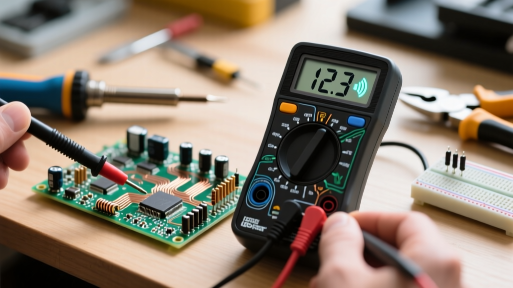
Once power is applied, systematic probing is required to trace the signal path through the timing network.
Verifying the Astable Oscillation
In an astable configuration, connect your oscilloscope probe to Pin 7 (Discharge). You should observe a sharp exponential decay (capacitor discharging through R2 and the internal transistor) followed by a slower exponential charge (through R1 and R2). If the waveform on Pin 7 looks like a clean square wave instead of an RC curve, your timing capacitor is likely open-circuit or missing entirely. Next, probe Pin 3 (Output). Note that the classic NE555 is not rail-to-rail; the HIGH output will typically be VCC minus 1.5V due to the internal Darlington transistor pair voltage drop. If your schematic relies on a true 5V logic HIGH from a 5V supply, you must use a CMOS variant like the TLC555 or add a pull-up resistor and an external logic buffer.
Checking Monostable Trigger Thresholds
For monostable (one-shot) schematics, the trigger pulse on Pin 2 must dip below 1/3 VCC to initiate the timing cycle. A common failure mode occurs when designers use a mechanical switch tied to VCC with a pull-down resistor to generate the trigger. Switch bounce can cause multiple rapid triggers. Furthermore, if the trigger pulse is held LOW for longer than the RC timing period dictated by Pin 6, the output will remain HIGH until the trigger is released. Ensure your schematic includes an RC differentiator network at the input to guarantee a clean, narrow trigger pulse.
Component-Level Failure Modes and the R1 Death Trap
One of the most destructive schematic errors involves the discharge resistor (R1) in an astable configuration. Pin 7 is essentially an NPN transistor collector tied to ground. When the internal flip-flop toggles, this transistor turns on, sinking current from VCC through R1 to ground.
If a designer attempts to achieve a very high frequency or a near-50% duty cycle by selecting an R1 value of 100Ω on a 12V supply, the instantaneous current through Pin 7 will be 120mA ($I = V/R$). The internal discharge transistor on a standard NE555 is typically rated for a maximum continuous current of 100mA to 200mA depending on the manufacturer. Exceeding this will cause thermal runaway, melting the silicon die and permanently shorting Pin 7 to ground. Rule of thumb: Always design R1 to limit discharge current to less than 10mA. For a 12V system, R1 should never be lower than 1.2kΩ.
Additionally, beware of capacitor leakage. If you are using cheap electrolytic capacitors for the timing network (C1), their inherent leakage current acts as a parallel resistor. As the capacitor charges toward 2/3 VCC, the leakage current can prevent the voltage from ever crossing the upper comparator threshold, resulting in a hung circuit where the output stays HIGH indefinitely. For timing values above 1µF, always use low-leakage tantalum, aluminum polymer, or stacked film capacitors.
Advanced References and Datasheet Insights
Troubleshooting an IC 555 schematic requires moving beyond basic wiring diagrams and understanding the semiconductor physics dictating the component's behavior. For deeper analysis of internal propagation delays, output stage sourcing/sinking limitations, and temperature drift characteristics, consult the following authoritative resources:
- Texas Instruments NE555 Datasheet - The definitive guide to absolute maximum ratings, internal block diagrams, and electrical characteristics across temperature gradients.
- Electronics Tutorials 555 Timer Guide - Excellent mathematical breakdowns of astable, monostable, and bistable configurations, including duty cycle limitations.
- Wikipedia: 555 Timer IC - A comprehensive historical and technical overview, including the critical differences between bipolar (NE555) and CMOS (TLC555/LMC555) architectures.
By rigorously validating your decoupling networks, respecting the current limits of the discharge transistor, and selecting appropriate dielectric materials for your timing capacitors, you can transform an erratic IC 555 schematic into a bulletproof, production-ready timing circuit.