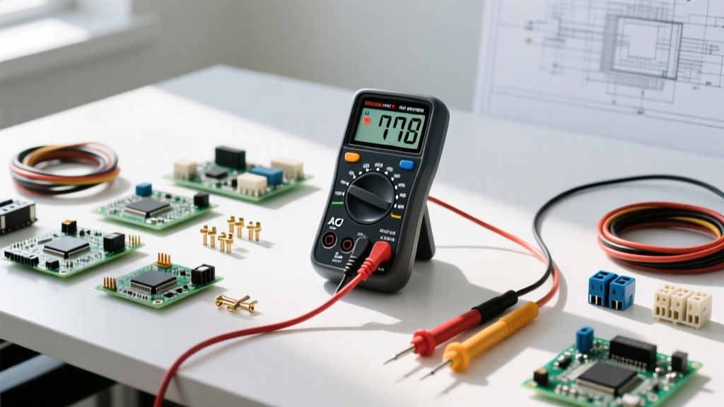

Phase 1: The Foundation – Understanding Your Multimeter's Voltage Modes
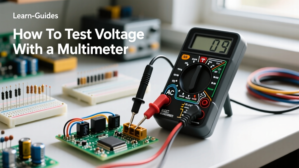
Learning how to check voltage using a multimeter is the most fundamental skill in electrical diagnostics, but true proficiency goes far beyond simply poking probes into a receptacle. Voltage is the electrical potential difference between two points, and measuring it accurately requires a deep understanding of your tool's internal architecture. Modern digital multimeters (DMMs), from budget-friendly options like the Klein Tools MM400 ($45) to industry-standard workhorses like the Fluke 117 ($220), utilize an analog-to-digital converter (ADC) with a standard input impedance of 10 megohms (10MΩ). This high impedance ensures the meter draws virtually zero current from the circuit, preventing the meter itself from altering the voltage you are trying to measure.
Before touching any live component, you must master the dial. The voltage settings are universally divided into two distinct domains:
- V⎓ (DC Voltage): Used for batteries, solar panels, automotive systems, and microcontroller logic boards (e.g., Arduino, ESP32). DC voltage flows in a single direction.
- V~ (AC Voltage): Used for mains power, household wiring, transformers, and heavy appliances. AC voltage oscillates, typically at 60Hz in North America and 50Hz in Europe.
Beginners often rely entirely on auto-ranging meters, which automatically select the correct measurement scale. While convenient, auto-ranging can be slow and may display erratic readings when measuring fluctuating signals. As you progress on this skill-building path, you will learn to manually select a range slightly higher than your expected voltage to lock the ADC and achieve faster, more stable readings.
Phase 2: Safety First – The 'One-Hand Rule' and CAT Ratings
Electricity is unforgiving. When measuring AC mains voltage, the risk of arc flash or lethal shock is real. According to OSHA Electrical Safety guidelines, establishing safe work practices is mandatory before any diagnostic work begins. The most critical physical habit you must develop is the 'One-Hand Rule'.
The One-Hand Rule: When probing live AC circuits, keep your non-dominant hand behind your back or in your pocket. If you accidentally touch a live conductor with your probe hand, this prevents the current from traveling across your chest and through your heart, drastically reducing the risk of ventricular fibrillation.
Equally important is understanding your multimeter's Category (CAT) rating. A CAT III 600V meter is not merely rated for 600 volts; it is tested to withstand transient overvoltage spikes (like a nearby lightning strike or heavy inductive load switching) up to 8,000 volts. For standard household receptacle testing, a CAT III meter is sufficient. For service entrance panels and outdoor utility connections, a CAT IV meter is strictly required. Never compromise on PPE; wear ANSI-rated safety glasses and voltage-rated gloves when working on panels above 50V.
Phase 3: Step-by-Step Execution – How to Check Voltage Using a Multimeter
Measuring DC Voltage (Batteries and Logic Boards)
Let us start with a practical scenario: testing a 12V lead-acid automotive battery. Insert the black probe into the COM (Common) jack and the red probe into the V/Ω jack. Set your dial to DC Voltage (V⎓).
- Surface Charge Check: Touch the red probe to the positive terminal and the black probe to the negative terminal. A healthy, resting battery should read between 12.4V and 12.7V. A reading of 12.0V indicates a 50% state of charge.
- Load Simulation: Voltage is only half the story. A battery can show 12.6V at rest but drop to 8V under the load of a starter motor due to internal resistance. Have an assistant crank the engine while you monitor the probes. If the voltage drops below 10.0V during cranking, the battery has a sulfated cell or excessive internal resistance and must be replaced.
Measuring AC Voltage (Mains and Appliances)
Testing a standard North American NEMA 5-15R wall receptacle requires a systematic approach to verify not just the presence of power, but the integrity of the grounding system. Set your meter to AC Voltage (V~) and select the 200V or 600V range.
- Hot to Neutral (Short slot to Long slot): Should read 115V to 125V. This confirms the main voltage supply.
- Hot to Ground (Short slot to Round hole): Should also read 115V to 125V. This confirms the equipment grounding conductor is properly bonded back to the panel.
- Neutral to Ground (Long slot to Round hole): Should read less than 2.0V (ideally 0.0V to 0.5V). A reading higher than 2.0V indicates a loose neutral connection somewhere in the branch circuit, which can cause severe damage to sensitive electronics due to voltage imbalance.
Phase 4: Diagnostic Intuition – Interpreting Ghost Voltage
As you advance from apprentice to expert, you will encounter anomalous readings that confuse beginners. The most common is 'ghost voltage' or 'phantom voltage'. Imagine you are testing a disconnected 14 AWG wire in a multi-conductor cable bundle and your high-impedance (10MΩ) multimeter reads 65V AC, even though the wire is entirely disconnected from the breaker.
This is not a real, dangerous voltage; it is capacitive coupling. The live wires running parallel to your disconnected wire act as a capacitor, inducing a harmless, low-current voltage onto the open wire. To diagnose this, you need a meter equipped with a LoZ (Low Impedance) mode. LoZ drops the meter's input impedance to around 3 kilohms (3kΩ), bleeding off the phantom capacitive charge and revealing the true voltage (0V). For a deeper dive into measurement anomalies, review the extensive guides on All About Circuits Measurement Techniques.
Phase 5: The Troubleshooting Matrix
Memorize this diagnostic matrix to quickly pivot from reading a number to identifying the root cause of an electrical fault.
| Reading Anomaly | Probable Cause | Pro-Troubleshooting Step |
|---|---|---|
| Fluctuating AC Voltage (e.g., 110V to 128V rapidly) | Loose neutral connection or heavy harmonic distortion from non-linear loads. | Measure Neutral-to-Ground. If it fluctuates wildly, tighten neutral bus bar connections in the sub-panel. |
| 12V Battery reads 10.5V at rest | Shorted or sulfated cell inside the battery casing. | Perform a conductance load test. If flooded, check the specific gravity of the electrolyte with a hydrometer. |
| 120V Receptacle reads 0V Hot-to-Neutral | Tripped GFCI upstream, open hot wire, or backstabbed receptacle failure. | Verify upstream GFCI reset. Remove receptacle cover and check if wires are pushed into backstab holes; move to screw terminals. |
| Reads 40V-80V on disconnected wire | Ghost voltage caused by capacitive coupling in parallel cable runs. | Switch multimeter to LoZ (Low Impedance) mode to bleed off phantom charge and confirm 0V. |
| 240V Dryer Outlet reads 120V on both hots to ground | Lost leg (open breaker pole or blown service fuse on one phase). | Measure Hot 1 to Hot 2. If it reads 0V, you have a lost phase. Check the main panel dual-pole breaker. |
Phase 6: Advancing Your Skills – Voltage Drop Testing
The ultimate test of your multimeter skills is moving beyond static voltage checks to dynamic voltage drop testing. A circuit might show a perfect 12.6V at the battery and 12.6V at the component when unplugged. However, when the component is turned on and draws current, the voltage at the component might plummet to 9V. Why? Because of hidden resistance in the wiring, corroded connectors, or failing ground straps.
According to Fluke's diagnostic best practices, voltage drop testing must be performed under load with the circuit energized and operating. To perform this:
- Turn the circuit ON so current is flowing.
- Set your DMM to DC Voltage.
- Place the red probe on the positive terminal of the power source, and the black probe on the positive terminal of the load (e.g., a headlight).
- The meter will now read the voltage lost across the positive wire. A healthy wire should drop less than 0.2V. A reading of 1.5V indicates severe corrosion or an undersized wire gauge.
- Repeat the process on the ground side (red probe on load negative, black probe on battery negative).
By mastering how to check voltage using a multimeter through this structured skill-building path, you transition from a passive observer of numbers to an active diagnostician capable of uncovering the hidden faults that plague complex electrical and electronic systems.