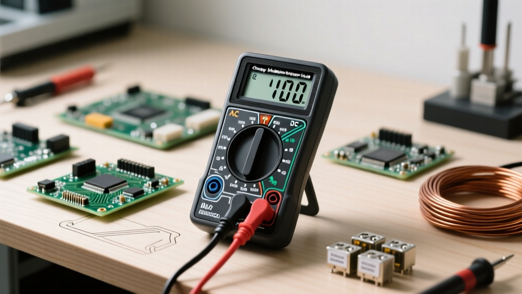

Understanding Voltage: The Electrical Pressure
Voltage is the electromotive force—or 'pressure'—that pushes electrons through a conductive path. Think of it like water pressure in a plumbing system: the higher the pressure, the more potential work the water can do. For any DIY electronics enthusiast, maker, or apprentice electrician, learning the proper technique for checking voltage multimeter measurements is the most critical foundational skill you will acquire. Whether you are troubleshooting a dead Arduino, testing a 12V LED strip, or verifying a wall outlet, your multimeter acts as the gauge that reveals the invisible forces at play.
However, voltage is not measured by breaking the circuit. Unlike current (Amps), which requires the multimeter to become part of the circuit path in series, voltage is always measured in parallel. You simply touch the probes across the two points you want to compare. This fundamental rule dictates how we set up our tools and approach our tests safely.
Anatomy of the Dial: Where to Set Your Probes
Before turning the dial, you must correctly insert your test leads. A standard digital multimeter (DMM) features three or four input jacks at the bottom. Misplacing your red probe is the most common—and sometimes most dangerous—beginner mistake.
- COM (Common): The black probe always goes here. This is your ground or reference point.
- VΩmA (Volts, Ohms, Milliamps): The red probe goes here for 99% of all voltage, resistance, and low-current tests. This port is protected by an internal fuse designed to handle the high impedance of voltage testing.
- 10A (10 Amps): The red probe goes here only when measuring high current. It is typically unfused or protected by a heavy-duty sand fuse.
The Deadly 10A Port Mistake
If you leave your red probe in the 10A port and attempt to measure voltage across a wall outlet or a battery, you are creating a dead short. Because the 10A port has near-zero resistance, connecting it in parallel across a voltage source will cause a massive spark, instantly blow the internal fuse, and potentially destroy the multimeter or cause severe arc flash burns. Always verify your red probe is in the VΩ port before checking voltage.
DC vs. AC Voltage: Which Setting Do You Need?
When checking voltage multimeter dials for the first time, beginners often confuse the alternating current (AC) and direct current (DC) symbols. Selecting the wrong mode will result in a reading of zero or erratic, fluctuating numbers.
| Feature | Direct Current (DC) | Alternating Current (AC) |
|---|---|---|
| Symbol on Dial | V with a solid and dashed line (V⎓) | V with a wavy line (V~) |
| Current Flow | Unidirectional (Constant) | Reverses direction periodically (50/60Hz) |
| Common Sources | Batteries, Solar Panels, USB, Arduino | Wall Outlets, Grid Power, Generators |
| Polarity Matters? | Yes (Red to +, Black to -) | No (Probes are interchangeable) |
Step-by-Step: Checking DC Voltage Safely
Let us walk through testing a standard 9V alkaline battery and a 5V microcontroller pin. According to SparkFun's comprehensive multimeter tutorial, auto-ranging meters will find the correct scale for you, but manual-ranging meters require you to select a ceiling higher than your expected voltage.
- Insert Probes: Black into COM, Red into VΩ.
- Set the Dial: Turn to the DC Voltage setting (V⎓). If manual-ranging, select the 20V scale (since 9V and 5V are below 20, but above the 2V scale).
- Connect in Parallel: Touch the black probe to the battery's negative terminal (or circuit ground). Touch the red probe to the positive terminal (or the 5V output pin).
- Read the Display: A fresh 9V battery will read between 9.3V and 9.6V. If it reads below 8.0V, it is effectively dead for high-draw applications. A 5V Arduino pin should read between 4.8V and 5.1V.
Pro-Tip: If you see a negative sign (e.g., -9.4V), do not panic. You simply have the probes reversed. The red probe is on the negative side, and the black is on the positive. The absolute voltage value is still accurate.
Step-by-Step: Checking AC Mains Voltage
Testing AC mains voltage (120V in North America, 230V in Europe/UK) introduces significant safety hazards. You are no longer dealing with harmless low-voltage electronics; you are interacting with the power grid.
- Inspect Your Probes: Ensure there are no cracks, exposed wires, or burn marks on the probe insulation. Compromised probes can be lethal.
- Set the Dial: Turn to AC Voltage (V~). Select the 200V or 600V range if your meter is manual-ranging.
- Test the Outlet: Insert one probe into the 'hot' (shorter) slot and the other into the 'neutral' (longer) slot. Because AC alternates, polarity does not matter; the meter will read correctly regardless of which probe goes into which slot.
- Verify Ground: Move the black probe to the round ground hole while keeping the red probe in the hot slot. You should read the same voltage (~120V). If you read 0V between hot and ground, your outlet has a dangerous open-ground fault.
The One-Hand Rule: When working near live mains power, keep one hand in your pocket. If you accidentally touch a live conductor, having both hands in the circuit path allows current to travel across your chest, potentially stopping your heart. Keeping one hand away ensures any accidental shock travels down your side to the ground, bypassing vital organs. For more on this, review the OSHA Electrical Safety Standards.
Decoding Display Errors: OL, Ghost Voltages, and Fluctuations
Beginners often misinterpret multimeter error codes as broken equipment. Here is how to translate the screen:
- 'OL' or '1' (Overload): This means the voltage exceeds the current range setting. If you are on the 2V scale and test a 12V battery, the meter protects itself by displaying OL. Simply turn the dial to a higher range (e.g., 20V).
- Ghost Voltages: When testing disconnected wires in a conduit, you might read 40V to 80V AC on a high-impedance digital meter. This is capacitive coupling from adjacent live wires. To confirm it is a 'ghost', plug a small incandescent bulb or a solenoid tester (Wiggy) into the circuit; the ghost voltage will instantly collapse to zero under load.
- Fluctuating Numbers: If testing an unregulated power supply or a noisy DC motor circuit, the last few digits will dance. This is normal. Look for meters with a 'Hold' button or a low-pass filter (LPF) to stabilize the reading.
Why CAT Ratings Matter for Your Safety
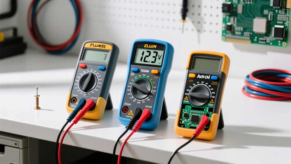
Not all multimeters are built to survive the grid. The Fluke CAT Ratings Guide outlines the Overvoltage Installation Categories (CAT I through CAT IV) that dictate a meter's ability to survive transient voltage spikes (like a lightning strike hitting a power line miles away).
- CAT I: Protected electronics, signal levels. (Not safe for wall outlets).
- CAT II: Single-phase receptacles, plug-in appliances, and portable tools.
- CAT III: Three-phase distribution, fixed motors, and building lighting systems.
- CAT IV: Primary supply levels, overhead lines, and utility meters.
If you are checking AC voltage at a residential wall outlet, your multimeter must be rated at least CAT II, though CAT III is the industry standard for professional safety. A cheap, unrated meter from a discount bin may measure 120V perfectly fine on a good day, but a transient spike can cause it to explode in your hands. Always check the stamp near the input jacks to verify your tool's CAT rating and maximum voltage tolerance before beginning any mains-level diagnostics.
Summary Checklist for Every Test
To ensure longevity of your equipment and personal safety, run through this mental checklist before every measurement: Probes in the correct ports (VΩ, not 10A)? Dial set to the correct current type (AC vs DC)? Range set higher than the expected voltage? By treating every circuit as live until proven otherwise, and relying on your multimeter's parallel measurement capabilities, you will diagnose electrical faults quickly, accurately, and safely.