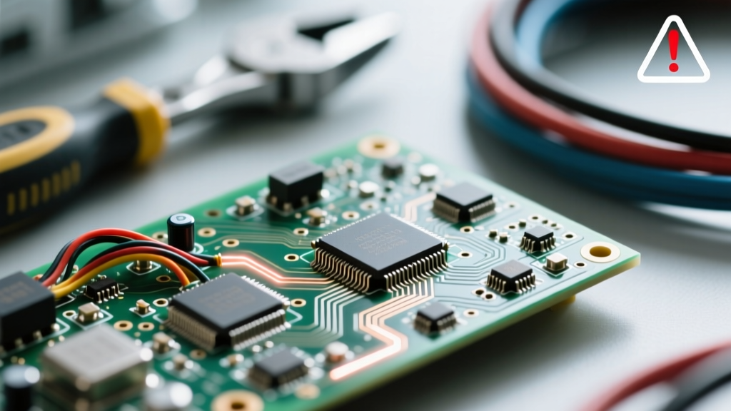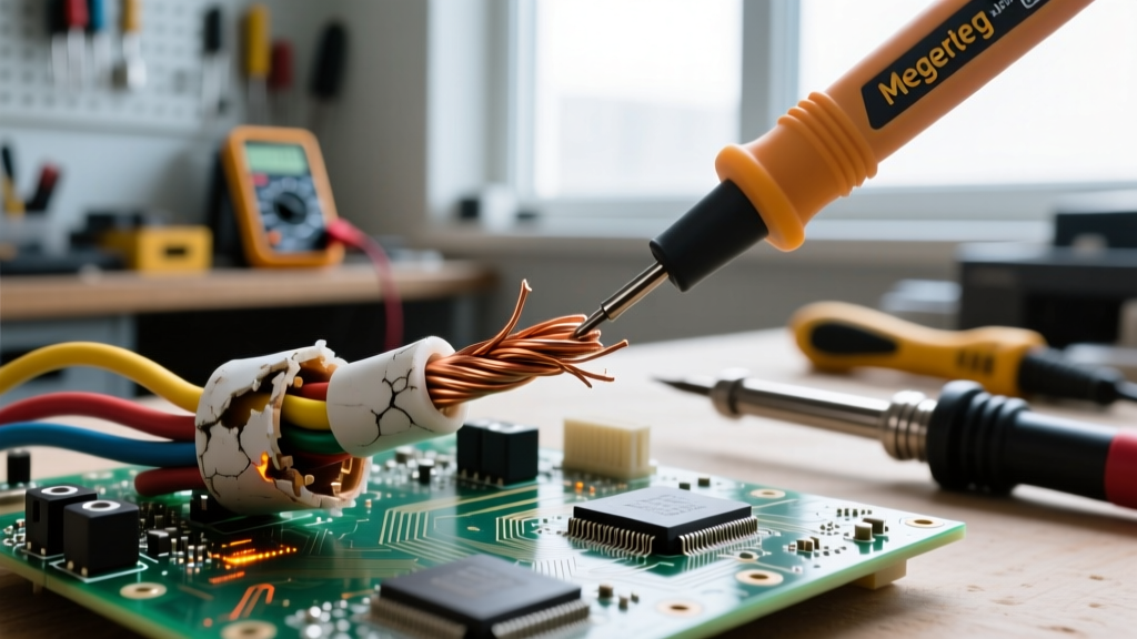

Electrical systems rarely fail due to complex design flaws; instead, catastrophic faults almost always originate at the material level. When troubleshooting electrical circuits, technicians often focus on active components like relays, breakers, and microcontrollers. However, the foundational reliability of any circuit depends entirely on the integrity of its conductors and insulators. A degraded dielectric material or an oxidized copper strand can introduce high-resistance faults, arcing, and eventual thermal runaway long before a breaker ever trips.
Troubleshooting these fundamental materials requires moving beyond simple digital multimeter (DMM) continuity checks. In this comprehensive diagnostic guide, we will explore the specific failure modes of conductors and insulators, the physics behind their degradation, and the advanced field-testing protocols required to isolate and resolve these hidden faults.
The Physics of Material Degradation
To effectively troubleshoot, one must understand the physical stresses placed on wiring. Conductors (typically copper or aluminum) are tasked with minimizing resistive losses (I²R heating) while carrying current. Insulators (such as PVC, XLPE, or PTFE) are tasked with containing the electric field and preventing leakage current to ground or adjacent phases.
Over time, thermal cycling, mechanical vibration, and ambient moisture attack these materials. Insulators suffer from dielectric breakdown and electrical tracking, where microscopic carbon paths form across the surface, allowing leakage current. Conductors suffer from galvanic corrosion, strand fatigue, and oxidation, which increases the cross-sectional resistance and creates localized hotspots.
Diagnostic Framework: Isolating the Fault
When investigating a suspected wiring fault, a systematic approach is critical to avoid misdiagnosing a failing wire as a bad load or a tripped breaker. Follow this triage framework:
Step 1: Visual and Thermal Triage
Before de-energizing the circuit, utilize a high-resolution thermal imager (such as the Fluke TiS75+) to scan the entire run of the wiring under full load.
- Insulation Hotspots: If a specific section of the wire jacket is hotter than the rest, it indicates internal dielectric leakage or tracking. The insulation is absorbing energy and converting it to heat.
- Termination Hotspots: Heat concentrated at lugs, wire nuts, or terminal blocks almost always indicates conductor oxidation, loose mechanical pressure, or galvanic corrosion between dissimilar metals.
Step 2: Insulation Resistance (IR) Testing
A standard DMM uses a 3V to 9V battery to check continuity, which is entirely insufficient for evaluating insulators. You must apply a high-voltage DC stress test using an insulation multimeter (megger). According to guidelines published by Fluke Corporation, applying 500V DC to a 600V-rated cable will reveal microscopic fissures and moisture ingress that a DMM will completely miss.
Insulator Failure Modes: Beyond the Jacket
When troubleshooting insulators, the failure is rarely as simple as "melted plastic." Modern dielectrics fail in highly specific, often invisible ways.
Electrical Tracking and Corona Discharge
In high-voltage or high-humidity environments, partial discharges (corona) can occur in microscopic voids within the insulation, such as in cross-linked polyethylene (XLPE). This ionizes the surrounding air, creating ozone and nitric acid, which chemically etches the insulation. Over time, this forms "water trees" or "electrical trees"—branching micro-channels that eventually bridge the conductor and the ground, resulting in a catastrophic short circuit.
Thermal and Chemical Degradation
Standard THHN (Thermoplastic High Heat-resistant Nylon-coated) wire is rated for 90°C in dry locations. However, if routed near steam lines or subjected to continuous harmonic overloading, the PVC plasticizers leach out. The insulation becomes brittle and cracks when subjected to the mechanical stress of thermal expansion. Conversely, PTFE (Teflon) insulators can withstand up to 250°C but are highly susceptible to cold-flow deformation if over-torqued in terminal blocks.
Conductor Degradation: The Hidden Resistance
While insulators fail by letting current escape, conductors fail by restricting current flow. This restriction manifests as voltage drop and localized heating. Below is a troubleshooting matrix for common conductor failures.
| Failure Mode | Primary Mechanism | Diagnostic Symptom | Corrective Action |
|---|---|---|---|
| Galvanic Corrosion | Electrolytic reaction between Copper and Aluminum in the presence of moisture. | Severe voltage drop at terminations; white/green powdery residue; thermal hotspot at lug. | Replace with bimetallic lugs, use AlumiConn connectors, and apply NOALOX antioxidant compound. |
| Strand Fatigue | Repeated mechanical flexing (e.g., in cable carriers or robotics) breaks individual fine strands. | Intermittent circuit operation; resistance spikes when the cable is bent; localized heating at the break. | Replace with high-flex continuous-duty cable (e.g., silicone-jacketed, ultra-fine stranding). |
| Aluminum Creep | Aluminum conductors slowly deform and relax under constant mechanical pressure from screw terminals. | Loose connections after 1-2 years of service; arcing sounds; nuisance breaker trips. | Retorque all aluminum connections to manufacturer specs; use CO/ALR rated devices. |
| Skin Effect Overheating | High-frequency harmonics force current to the outer edge (skin) of the conductor, increasing effective resistance. | Neutral conductors in 3-phase systems overheating despite balanced loads; premature insulation melting. | Derate the neutral conductor by 200% or use K-rated transformers to mitigate triplen harmonics. |
Advanced Field Testing Protocols
To definitively prove the health of conductors and insulators, technicians must rely on standardized testing protocols outlined by the InterNational Electrical Testing Association (NETA). Two critical tests should be in every troubleshooter's repertoire:
The Polarization Index (PI) Test
The PI test is a time-resistance method used to evaluate the moisture content and overall health of thick insulation (typically in motors, generators, and heavy feeders).
- Apply a DC test voltage (e.g., 1000V) using a tool like the Megger MIT485/2.
- Record the insulation resistance at exactly 1 minute.
- Leave the voltage applied and record the resistance again at exactly 10 minutes.
- Divide the 10-minute reading by the 1-minute reading.
Step-Voltage Testing
For troubleshooting suspected physical damage to conductors (like a pinched cable under a concrete slab), the Step-Voltage test is highly effective. The test voltage is increased in increments (e.g., 500V, 1000V, 1500V, 2000V) at one-minute intervals. If the insulation is healthy, the resistance should remain relatively stable or increase as the dielectric absorbs charge. If the insulation has a physical fault or crack, the resistance will abruptly plummet at a specific voltage threshold, pinpointing the dielectric's exact breakdown limit.
Preventative Maintenance & Material Selection
The best troubleshooting strategy is proactive material selection based on the specific environmental stressors of the installation. Understanding the dielectric strength (measured in Volts per mil, or V/mil) and thermal limits of various insulators prevents premature failures.
- PVC (THHN/THWN-2): Dielectric strength of ~1,200 V/mil. Excellent for standard commercial wiring but highly susceptible to UV degradation and plasticizer loss in high-heat environments.
- XLPE (XHHW-2): Dielectric strength of ~500-700 V/mil. While the raw V/mil is lower than PVC, its cross-linked molecular structure provides vastly superior thermal stability (up to 90°C wet/dry) and resistance to chemical solvents. Ideal for industrial motor feeds.
- PTFE (Teflon): Dielectric strength of ~1,000 V/mil. Chemically inert and capable of withstanding 250°C. Mandatory for aerospace, high-temperature ovens, and sensitive analog signal wiring where outgassing cannot be tolerated.
- EPR (Ethylene Propylene Rubber): Highly resistant to corona discharge and water treeing. The Copper Development Association and industry standards frequently recommend EPR-insulated copper conductors for medium-voltage underground distribution where moisture is a constant threat.
Conclusion
Troubleshooting conductors and insulators requires a shift in mindset from simple circuit logic to material science. By utilizing thermal imaging to spot resistive anomalies, employing high-voltage DC meggers to stress-test dielectrics, and understanding the electrochemical realities of galvanic corrosion, technicians can predict and prevent catastrophic failures. Always adhere to NETA testing standards and ensure that the replacement materials you select are chemically and thermally matched to the harsh realities of the field environment.