
The Core Question: What Is the Difference Between Insulators and Conductors?
When designing circuits, sizing wire, or troubleshooting electrical faults, understanding material properties is non-negotiable. At the most fundamental level, the question of what is the difference between insulators and conductors comes down to electron mobility. Conductors are materials that permit the free flow of electrical current, while insulators resist this flow, confining the current to its intended path. However, in professional electrical engineering and DIY wiring, this binary definition is insufficient. To truly master wire fundamentals, we must examine atomic architecture, energy band gaps, dielectric strength, and thermal limits.
This comprehensive reference guide and chart breaks down the physics, practical applications, and failure modes of the materials you work with every day, from standard THHN copper wiring to high-voltage XLPE underground cables.
Atomic Architecture and Energy Band Theory
To understand macroscopic electrical behavior, we must look at the quantum level. According to Georgia State University's HyperPhysics, the electrical properties of solid materials are dictated by their energy band structure—specifically, the relationship between the valence band (where electrons are bound to atoms) and the conduction band (where electrons are free to move and carry current).
The Band Gap Divide
- Conductors: In materials like copper and silver, the valence and conduction bands overlap. There is effectively zero band gap (0 eV). Even a minuscule applied voltage provides enough energy to push valence electrons into the conduction band, resulting in immediate current flow.
- Insulators: In materials like PVC, glass, and mica, there is a massive energy gap (typically greater than 3.0 to 5.0 eV) between the valence and conduction bands. Under normal operating voltages, electrons cannot bridge this gap, meaning no current flows.
- Semiconductors: Materials like silicon sit in the middle with a small band gap (around 1.1 eV), allowing them to act as insulators at low temperatures and conductors when energized or doped.
Expert Insight: No insulator is perfect. If the applied voltage exceeds the material's dielectric strength, it will forcefully rip electrons across the band gap, causing catastrophic dielectric breakdown.
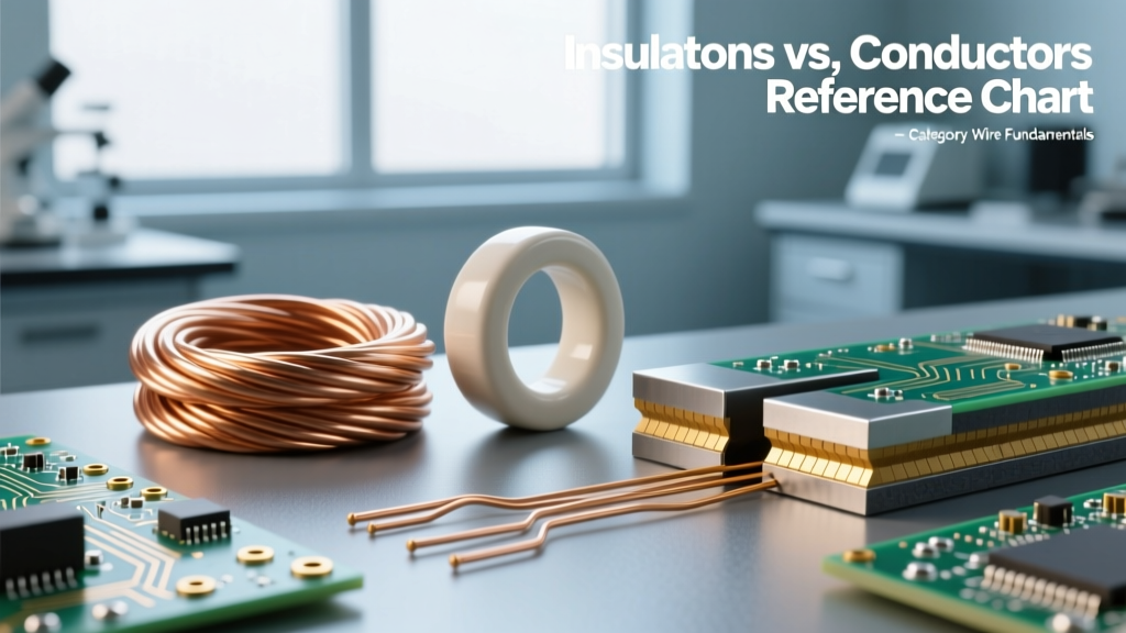
Master Reference Chart: Conductors vs. Insulators in Wiring
The following chart provides critical engineering data for the most common conductors and insulators used in residential, commercial, and industrial wiring. Data is aggregated from standard engineering references, including The Engineering Toolbox.
| Material | Role | Electrical Conductivity | Dielectric Strength | Max Operating Temp | Common Application |
|---|---|---|---|---|---|
| Silver | Conductor | 63.0 MS/m | N/A | 961°C | High-freq RF, aerospace contacts |
| Copper | Conductor | 59.6 MS/m | N/A | 1085°C | Standard branch wiring (THHN, NM-B) |
| Aluminum | Conductor | 37.7 MS/m | N/A | 660°C | Service entrance, transmission lines |
| PVC | Insulator | ~10^-14 S/m | 40 kV/mm | 75°C - 105°C | Standard residential NM-B, THHN jacket |
| XLPE | Insulator | ~10^-16 S/m | 50 kV/mm | 90°C - 105°C | Medium/High voltage underground feeder |
| PTFE (Teflon) | Insulator | ~10^-18 S/m | 60 kV/mm | 260°C | Aerospace, high-temp thermocouple wire |
| Mica | Insulator | ~10^-16 S/m | 118 kV/mm | 600°C+ | High-voltage switchgear, heating elements |
Conductor Deep Dive: Copper, Aluminum, and Silver
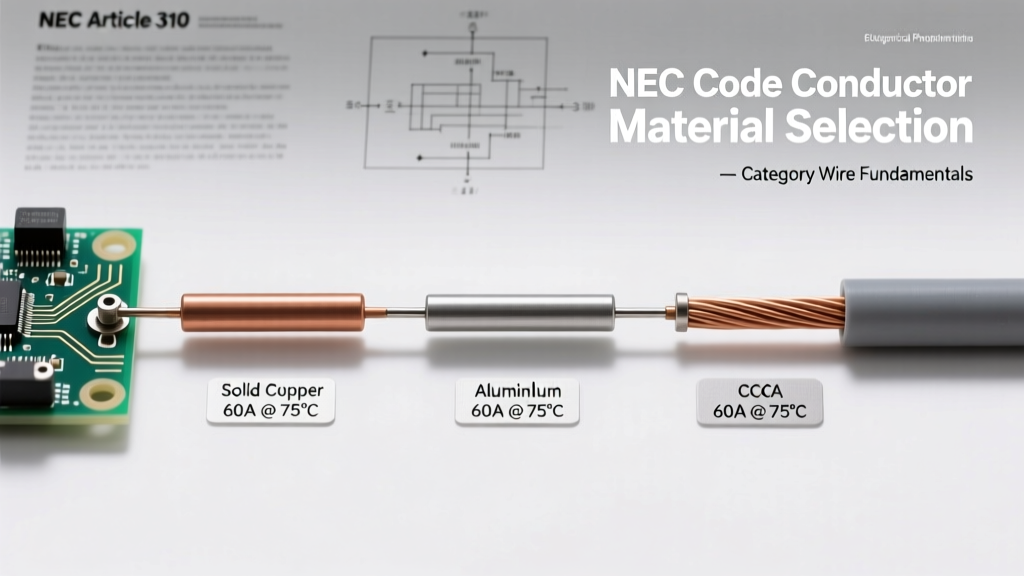
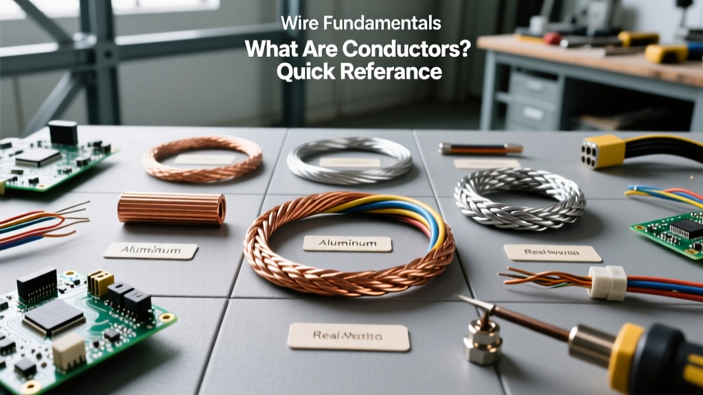
While silver boasts the highest electrical conductivity (63.0 MS/m), its cost prohibits widespread use in building wiring. Therefore, copper (59.6 MS/m) remains the undisputed king of residential and commercial electrical systems. Copper offers an optimal balance of high conductivity, excellent tensile strength, and high thermal mass, which allows it to absorb short-circuit heat without melting.
Aluminum (37.7 MS/m) is lighter and cheaper but presents unique challenges. Because its conductivity is roughly 61% that of copper, aluminum wire must be upsized (e.g., using 2 AWG aluminum instead of 4 AWG copper for a 100-amp service). Furthermore, aluminum oxidizes rapidly when exposed to air. This aluminum oxide layer is highly resistive and can cause high-resistance connections, leading to thermal runaway and fires if not treated with antioxidant paste (like Noalox) and torqued to manufacturer specifications.
Insulator Deep Dive: PVC, XLPE, and PTFE
Insulators do not just prevent shock; they dictate the thermal and chemical limits of a cable.
- PVC (Polyvinyl Chloride): The workhorse of modern wiring. It is flexible, cheap, and inherently flame-retardant due to its chlorine content. However, PVC degrades under prolonged UV exposure and emits toxic hydrochloric acid gas when burned.
- XLPE (Cross-Linked Polyethylene): By cross-linking the polymer chains, XLPE achieves superior thermal stability and a higher dielectric strength (approx. 50 kV/mm) compared to standard PE. It is the standard for medium and high-voltage underground distribution cables because it resists moisture and electrical treeing.
- PTFE (Polytetrafluoroethylene / Teflon): Used in extreme environments. PTFE is virtually immune to chemical attack and can withstand continuous temperatures up to 260°C. It is heavily used in military and aerospace wiring where weight and thermal resilience are critical.
The Thermal vs. Electrical Conductivity Paradox
A common misconception among beginners is that all electrical insulators are also thermal insulators. While this is true for most polymers (like PVC and rubber), it is fundamentally false in advanced materials science.
According to Encyclopedia Britannica's principles of conduction, thermal and electrical conductivity are linked in metals by the Wiedemann-Franz law (both are carried by free electrons). However, in non-metals, heat is conducted via phonons (lattice vibrations). Diamond and Beryllium Oxide (BeO) are perfect examples of the paradox: they are exceptional electrical insulators (band gaps > 5.0 eV) but possess thermal conductivities that rival or exceed copper. This makes them invaluable as heat-sink insulators in high-power semiconductor packaging, where electrical isolation and rapid heat dissipation must coexist.
Troubleshooting Insulation Failure and Dielectric Breakdown
Understanding what separates insulators from conductors is only half the battle; knowing how insulators fail and become conductors is where true expertise lies. Insulation failure rarely happens instantly; it is usually a progressive degradation.
1. Electrical Treeing and Partial Discharge
In high-voltage cables (like XLPE), microscopic voids or impurities in the insulation can cause localized electric field concentrations. This leads to partial discharge (PD)—tiny, localized sparks that do not fully bridge the gap. Over time, PD hollows out microscopic, fern-like channels in the polymer known as 'electrical trees.' Once a tree bridges the conductor and the ground shield, catastrophic dielectric breakdown occurs.
2. Surface Tracking and Moisture Ingress
In outdoor or damp environments, dirt and moisture accumulate on the surface of insulators (like ceramic standoffs or PVC conduit). Water is a conductor. This creates a resistive leakage path along the surface, known as 'tracking.' The resulting micro-arcing generates heat, which carbonizes the insulator surface. Carbon is a conductor, which further accelerates the leakage current until a full short circuit flashes over the surface.
3. Thermal Runaway
Insulators have a negative temperature coefficient of resistance. As an overloaded wire heats up, the insulation's resistivity drops. If the heat generated by the conductor exceeds the insulation's thermal rating (e.g., pushing a 60°C rated wire to 90°C), the insulation softens, degrades, and its dielectric strength plummets, eventually leading to a ground fault.
Summary
Ultimately, the difference between insulators and conductors is defined by quantum band gaps and macroscopic electron mobility. Conductors (Copper, Aluminum) are chosen for their low resistance and high thermal mass, while insulators (PVC, XLPE, Mica) are selected based on their dielectric strength, thermal ratings, and environmental resilience. By referencing the material properties and failure modes outlined in this chart, electricians and engineers can design safer, more reliable, and longer-lasting electrical systems.