
The Core Concept: What Exactly is Alternating Current Power?
When you plug a lamp, a power tool, or an oscilloscope into a standard wall outlet, you are tapping into alternating current power (AC). Unlike Direct Current (DC), where electrons flow steadily in a single direction from the negative to the positive terminal, AC power forces electrons to oscillate back and forth. This rapid reversal of direction is not a design flaw; it is a highly engineered feature that makes modern electrical grids and long-distance power transmission possible.
For DIY electronics enthusiasts and hobbyists transitioning from low-voltage DC projects (like Arduino or Raspberry Pi circuits) to mains-voltage AC projects (like smart home relays or custom lighting rigs), understanding the physics and safety parameters of AC is non-negotiable. Misunderstanding AC waveforms can lead to catastrophic component failure, inaccurate measurements, or severe electrical shock.
The Sine Wave: Visualizing Electron Flow
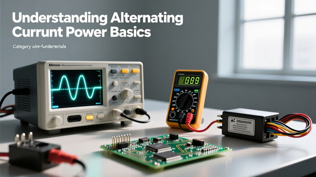
Alternating current power is generated by rotating a magnetic field inside a coil of wire (an alternator). This rotational motion naturally produces a sine wave. In a standard North American 60Hz system, the voltage starts at zero, rises to a positive peak, falls back through zero to a negative peak, and returns to zero. This entire sequence is one cycle, and it repeats 60 times every second.
The point where the waveform crosses the zero-voltage line is called the zero-crossing. This brief moment of zero potential is incredibly important in electrical engineering, as it is the exact moment when AC arcs naturally extinguish in switches and relays, a feature that DC circuits inherently lack.
Peak vs. RMS: The Voltage Numbers That Actually Matter
One of the most common beginner mistakes when working with alternating current power is assuming that a '120V' outlet actually supplies a constant 120 volts. It does not. The 120V figure is the Root Mean Square (RMS) voltage, an average that represents the equivalent heating power of a 120V DC source.
The actual peak voltage of a 120V RMS sine wave is significantly higher. You can calculate it using the formula:
V_peak = V_rms × √2
Therefore, 120V × 1.414 = 169.7V peak. When you select insulation for wires, capacitors for filtering, or semiconductors like TRIACs for switching, you must ensure their breakdown voltage ratings exceed the 170V peak, not just the 120V RMS. Failing to account for peak voltage is a primary cause of blown capacitors in beginner AC-to-DC power supply builds.
Why Your Multimeter Needs to be 'True RMS'
If you measure a pure sine wave with a cheap, average-responding multimeter, it will multiply the average voltage by a fixed constant (1.11) to display the RMS value. However, modern alternating current power is rarely a perfect sine wave. Non-linear loads like LED drivers, computer power supplies, and variable frequency drives distort the waveform, creating 'harmonics'. According to Fluke's testing guidelines, an average-responding meter can be off by up to 40% when measuring these distorted waves. For accurate diagnostics in modern homes, a True RMS multimeter is mandatory, as it calculates the actual heating value of the complex waveform.
The Global Divide: 50Hz vs. 60Hz Frequency Standards
The frequency of alternating current power dictates how many cycles occur per second, measured in Hertz (Hz). The world is largely split into two camps, a historical hangover from the early days of electrification and the 'War of the Currents'.
| Region | Standard Voltage (RMS) | Frequency | Common Plug Types | Physical Implications |
|---|---|---|---|---|
| North America | 120V / 240V | 60 Hz | NEMA 1-15, NEMA 5-15 | Motors run faster; transformers can be slightly smaller. |
| Europe / Asia | 230V | 50 Hz | Schuko (Type F), BS 1363 | Higher voltage allows thinner wires; motors run 20% slower. |
| Japan | 100V | 50 Hz & 60 Hz | Type A / B | Split grid: East is 50Hz, West is 60Hz. |
Why does frequency matter to a DIYer? If you import a 50Hz AC motor or transformer from Europe and run it on a 60Hz North American supply, the motor will run 20% faster and potentially overheat due to increased eddy current losses. Conversely, running a 60Hz transformer on 50Hz power can cause the magnetic core to saturate, leading to excessive heat and eventual failure.
Why the Grid Uses AC Instead of DC for Transmission
While Thomas Edison championed DC, Nikola Tesla and George Westinghouse proved that alternating current power was vastly superior for the electrical grid. The reason boils down to basic physics and the invention of the transformer.
Power loss in a transmission wire is calculated as P_loss = I²R (Current squared multiplied by Resistance). To deliver a specific amount of power (P = V × I), you can either use high current and low voltage, or low current and high voltage. Because power loss scales with the square of the current, it is vastly more efficient to transmit power at incredibly high voltages (up to 765,000V) and very low currents.
As noted by the U.S. Department of Energy, AC power can be easily stepped up to these massive transmission voltages and stepped back down to safe 120V/240V levels for residential use using simple, highly efficient transformers. Historically, DC could not be easily transformed, though modern High-Voltage Direct Current (HVDC) technology is now making a comeback for ultra-long-distance undersea cables.
Practical DIY Implications: Wiring and Safety for AC Circuits
When sizing wires and building enclosures for alternating current power, the rules are much stricter than for low-voltage DC. The National Electrical Code (NEC) governs these practices to prevent fires and electrocution.
Selecting the Right Wire Gauge for AC Loads
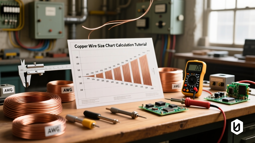
For standard 120V AC branch circuits in a DIY workshop or home automation panel, wire sizing is based on ampacity and breaker size. A 15-amp circuit requires a minimum of 14 AWG copper wire, while a 20-amp circuit mandates 12 AWG. Unlike DC circuits where voltage drop over short distances is the primary concern, AC wire sizing focuses heavily on thermal limits and breaker coordination.
Myth Busting: The Skin Effect. Many beginners read about the 'skin effect'—where high-frequency AC travels only on the outer surface of a wire—and assume they need special stranded or Litz wire for 60Hz mains power. At 60Hz, the skin depth in copper is roughly 8.5mm. Since standard house wire (even thick 2 AWG) has a radius much smaller than 8.5mm, the skin effect is completely negligible at mains frequencies. Standard solid or stranded THHN copper is perfectly optimal.
Grounding and Bonding in AC Systems
In DC electronics, 'ground' simply means the 0V reference point. In alternating current power systems, 'ground' is a literal physical connection to the earth. The Equipment Grounding Conductor (the bare copper or green wire) does not carry current under normal operation. Its sole purpose is to provide a low-resistance path back to the panel to trip the breaker instantly if a live 'hot' wire touches a metal chassis. Never use the AC earth ground as a current-carrying return path for your DIY circuits; this creates a severe shock hazard and will trip GFCI/RCD breakers.
Common Beginner Mistakes When Working with AC Power
- Mismatching Switch Ratings: A toggle switch rated for '15A 12V DC' might only be rated for '3A 120V AC'. DC arcs are continuous and require wider internal gaps or magnetic blowouts to extinguish. Using a DC-only switch on an AC circuit might work temporarily, but using an AC-rated switch to break a high-voltage DC load will result in a sustained plasma arc that will melt the switch and start a fire.
- Ignoring Isolation: When probing alternating current power with an oscilloscope, beginners often clip the scope's ground lead to the AC 'hot' wire. Because oscilloscopes are earth-grounded through their power cord, this creates a direct short circuit through the probe, exploding the probe tip and potentially destroying the scope. Always use differential probes or isolate the device under test.
- Using DC Capacitors on AC Lines: Electrolytic capacitors are polarized. If you place a standard DC electrolytic capacitor directly across an AC line, the reverse voltage during the negative half-cycle will rapidly destroy the dielectric layer, causing the capacitor to vent or explode. Always use non-polarized film or ceramic capacitors rated for AC voltage (specifically X1/X2 or Y1/Y2 safety-rated capacitors) when connecting directly across mains power.
Mastering alternating current power requires respecting its invisible hazards and understanding the mathematical realities of RMS, peak voltages, and frequency. By applying these fundamentals, you can safely bridge the gap between low-voltage microcontrollers and high-voltage mains automation.
For deeper reading on AC wave mechanics and phase angles, the All About Circuits textbook on Alternating Current remains one of the best free resources for visualizing how inductance and capacitance react to sine waves.