
The Reality of 600 Amp Capacity: Why Single Conductors Fail
When engineers and electricians search for a 600 amp wire size, they often encounter a fundamental misunderstanding of the American Wire Gauge (AWG) system. The AWG scale technically maxes out at 4/0 (or 0000). Beyond this threshold, the electrical industry transitions to measuring cross-sectional area in thousands of circular mils (kcmil or MCM). However, you cannot simply purchase a single '600 kcmil' or '800 kcmil' wire and connect it to a 600-amp breaker. The physical and legal limitations of electrical terminations make single-conductor 600A runs practically impossible in standard commercial applications.
The limiting factor is not the wire itself, but the termination points. According to NFPA 70 (National Electrical Code) Section 110.14(C), the ampacity of a conductor must be based on the lowest temperature rating of any connected termination, conductor, or device. While a single 1000 kcmil copper conductor boasts an ampacity of 615A in the 90°C column, standard 600A breakers, lugs, and busbars are almost universally rated for 75°C. In the 75°C column, that same 1000 kcmil copper wire is only rated for 545 amps. Therefore, to safely and legally deliver 600 amps, you must utilize parallel conductor configurations.
NEC Paralleling Rules and the Conduit Grouping Strategy
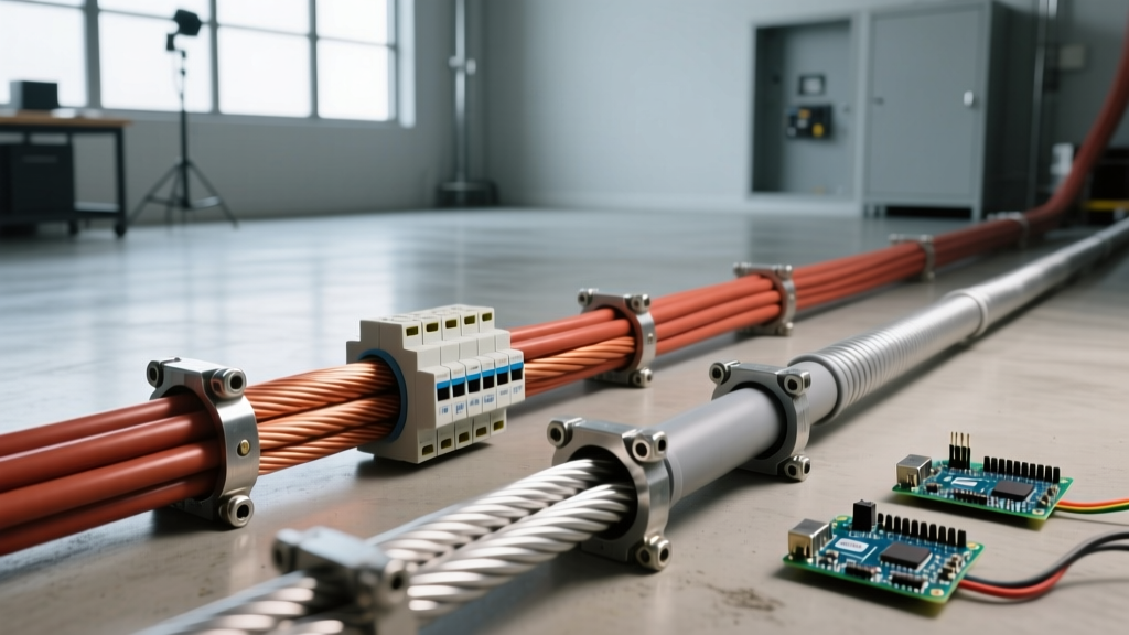
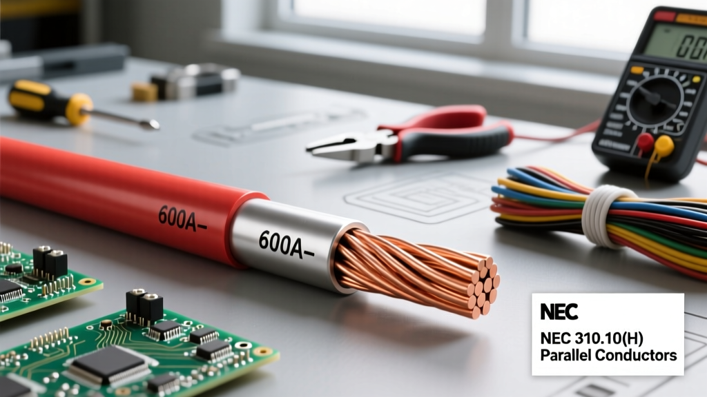
To achieve a 600 amp wire size rating, NEC Article 310.10(H) permits conductors sized 1/0 AWG and larger to be run in parallel. This means you can split the current across multiple wires per phase. However, paralleling introduces strict installation rules that dictate how these wires are routed through raceways.
Expert Insight: NEC 300.3(B) requires all conductors of the same circuit to be grouped together to prevent inductive heating. You cannot run Phase A in one conduit and Phase B in another. Furthermore, if you place multiple parallel sets in a single conduit, you trigger NEC 310.15(C)(1) ampacity adjustment factors (derating) for having more than three current-carrying conductors in a single raceway.
The industry-standard solution for a 600A feeder is to use multiple conduits, with each conduit containing one complete set of parallel conductors (Phase A, Phase B, Phase C, Neutral, and Ground). This maintains inductive balance while avoiding the severe thermal derating penalties of cramming 10 to 15 massive conductors into a single pipe.
Copper vs. Aluminum: 600 Amp Configurations Compared
Choosing between copper and aluminum for a 600A service involves balancing upfront material costs, long-term thermal stability, weight, and conduit space. Below is a comparison of the most common NEC-compliant parallel configurations used to achieve a 600 amp wire size.
| Configuration | Material | 75°C Ampacity (Total) | Approx. Weight (per 1000ft, 3-phase) | Relative Cost |
|---|---|---|---|---|
| 2 sets of 350 kcmil | Copper | 620A (2 x 310A) | ~3,200 lbs | $$$$$ |
| 3 sets of 4/0 AWG | Copper | 690A (3 x 230A) | ~2,150 lbs | $$$$ |
| 2 sets of 500 kcmil | Aluminum | 620A (2 x 310A) | ~1,050 lbs | $$ |
| 3 sets of 250 kcmil | Aluminum | 615A (3 x 205A) | ~880 lbs | $ |
Configuration A: Dual Parallel Copper (2x 350 kcmil)
Using two sets of 350 kcmil THHN copper is a favorite among engineers designing data centers or critical infrastructure where spatial constraints in switchgear are tight. Copper's superior conductivity allows for smaller lugs and tighter bending radii. However, the sheer weight of copper makes pulling these conductors through vertical risers a logistical challenge, often requiring motorized winches and specialized pulling lubricants.
Configuration B: Triple Parallel Aluminum (3x 250 kcmil)
For long-distance runs from a utility transformer to a commercial main distribution panel, aluminum is the undisputed king of cost-efficiency. Three sets of 250 kcmil aluminum provide a robust 615A capacity at 75°C. While aluminum requires larger conduit diameters and the mandatory application of anti-oxidant inhibitors (like Noalox) at terminations, the material savings can easily exceed $15,000 on a 500-foot feeder run compared to the copper equivalent. Refer to the Cerrowire Ampacity Tables for exact temperature and insulation adjustments.
Voltage Drop and Distance Considerations
When sizing a 600 amp wire, ampacity is only half the battle; voltage drop is the other. A 600A load at 480V three-phase represents nearly 500 kilowatts of power. The NEC recommends a maximum voltage drop of 3% for feeders. If your 600A service is located more than 250 feet from the source, standard ampacity-sized parallel runs will likely result in unacceptable voltage drop, causing motors to overheat and sensitive electronics to fault.
To combat this, engineers must oversize the conductors. For example, if a 3x 250 kcmil Aluminum setup satisfies the 600A thermal requirement, a 400-foot run might force you to upgrade to 3x 350 kcmil or even 3x 400 kcmil Aluminum solely to maintain voltage parameters. Always calculate voltage drop using the specific alternating-current resistance (AC impedance) values found in NEC Chapter 9, Table 9, rather than relying on basic DC resistance formulas.
Conduit Fill and Bending Radius Limitations
Physical installation constraints frequently dictate the final 600 amp wire size selection. Chapter 9 of the NEC limits conduit fill to 40% for three or more conductors. If you select the 3x 4/0 Copper configuration, you are dealing with 15 individual conductors (3 phases + neutral + ground, multiplied by 3 sets). Even when split across three separate conduits (5 conductors per conduit), 4/0 AWG THHN requires a minimum of 2-inch PVC Schedule 80 or 2-inch rigid metal conduit per set.
Furthermore, large kcmil wires resist bending. NEC Table 300.34 mandates strict minimum bending radii to prevent damage to the conductor insulation and internal shielding. A 500 kcmil aluminum conductor requires a bending radius of up to 13 inches depending on the shielding type, meaning your switchgear knockouts and pull boxes must be exceptionally deep to accommodate the physical footprint of the wire.
Termination Torque and Thermal Failure Modes
The most common failure point in a 600A parallel feeder is not the wire melting in the conduit; it is the termination lug overheating due to improper torque. NEC 110.14(D) explicitly requires the use of calibrated torque tools to achieve the exact pound-inch or pound-foot specifications listed by the equipment manufacturer.
For a 350 kcmil copper lug, the required torque often exceeds 40 ft-lbs. If an installer uses an uncalibrated wrench and under-tightens the lug, the increased contact resistance will generate intense localized heat. Under a continuous 300A load per leg, a loose lug can easily reach temperatures exceeding 300°F, eventually melting the lug barrel, degrading the THHN insulation, and triggering a catastrophic arc flash event. Always mandate post-installation thermal imaging scans during the first 30 days of full-load operation to verify that all parallel terminations are sharing current equally and remaining within safe thermal thresholds. For detailed hardware specifications, consult resources from major lug manufacturers like ILSCO.
Summary: Selecting Your 600A Feeder
There is no single '600 AWG' wire. Achieving a 600 amp wire size requires a deliberate choice between parallel copper and parallel aluminum. Choose dual 350 kcmil copper for tight switchgear spaces and critical infrastructure where budget is secondary to spatial efficiency. Choose triple 250 kcmil aluminum for long-distance utility feeders where weight reduction and massive material savings are paramount. Always respect NEC paralleling rules, separate your conduit sets to avoid inductive heating, and use calibrated torque tools on every single termination.