
Why TFT_eSPI Outperforms Standard GFX Libraries
For makers and engineers building GUIs on ESP32 and ESP8266 microcontrollers, the TFT_eSPI library by Bodmer is the undisputed gold standard. Unlike the ubiquitous Adafruit_GFX, which relies on slower, generalized SPI bit-banging or standard transactions, TFT_eSPI leverages the ESP32’s Direct Memory Access (DMA) and hardware SPI peripherals. This configuration guide will walk you through the notoriously tricky User_Setup.h file, ensuring you extract maximum frame rates from your ILI9341, ST7789, or GC9A01 displays.
According to the official TFT_eSPI GitHub repository, properly configuring DMA can yield rendering speeds up to 10 times faster than legacy libraries. This means your CPU is freed from pushing individual bytes to the display, allowing it to handle WiFi stack operations, sensor polling, and complex UI logic while the screen updates in the background. However, this massive performance gain comes at the cost of a rigid, compile-time configuration matrix that trips up many beginners.
Anatomy of the User_Setup.h File
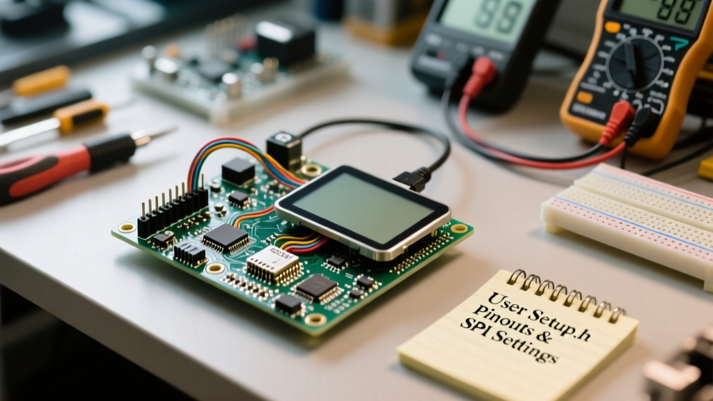
The most common point of failure for beginners is treating TFT_eSPI like a standard runtime-configurable library. You cannot define your pins, resolution, or display driver in the setup() function of your Arduino sketch. Every hardware parameter must be hardcoded into the User_Setup.h file before the library compiles. If you modify this file after your first compilation, the Arduino IDE may cache the old object files, leading to phantom bugs. Always clear your build cache or force a full recompile after changing setup parameters.
Pro-Tip for PlatformIO Users: If you use PlatformIO, do not edit the library's internalUser_Setup.h. Instead, pass your configuration flags directly via thebuild_flagsdirective in yourplatformio.inifile. This prevents your custom pinouts from being overwritten when the library manager fetches updates.
Step 1: Defining the Display Driver and Resolution
Inside User_Setup.h, locate the driver section. You must uncomment only one display driver. Uncommenting multiple drivers (e.g., leaving both ILI9341 and ST7789 active) will result in severe compilation errors, duplicate memory allocation failures, or a completely garbled framebuffer.
// #define ILI9341_DRIVER
#define ST7789_DRIVER
// #define GC9A01_DRIVER
Next, define the exact physical resolution of your panel. Note that many cheap 1.3" or 1.54" ST7789 displays have internal framebuffer offsets that require specific width and height definitions to prevent edge clipping and coordinate misalignment.
#define TFT_WIDTH  240
#define TFT_HEIGHT 280 // Use 280 for 1.69" ST7789, 240 for standard 2.0"
Step 2: Mapping ESP32 Hardware SPI Pins
The ESP32 features two primary SPI buses accessible to users: VSPI and HSPI. By default, TFT_eSPI targets the VSPI bus. If you are using a development board where VSPI pins are occupied by onboard flash, PSRAM, or antennas, you must switch to HSPI.
To use custom pins, uncomment the TFT_MISO, TFT_MOSI, TFT_SCLK, and TFT_CS definitions. If you leave them commented out, the library defaults to the ESP32's VSPI hardware pins.
// ESP32 VSPI Default Pinout
// #define TFT_MISO 19
// #define TFT_MOSI 23
// #define TFT_SCLK 18
// #define TFT_CS   5
For HSPI configuration, you must explicitly define the pins and enable the HSPI port flag:
#define USE_HSPI_PORT
#define TFT_MISO 12
#define TFT_MOSI 13
#define TFT_SCLK 14
#define TFT_CS   15
For a deeper understanding of ESP32 peripheral multiplexing and bus locking, refer to the Espressif SPI Master API documentation.
Reference Matrix: Common TFT Drivers and Configurations
Use this matrix to quickly identify the correct macros for your specific display module.
| Driver IC | Typical Resolution | Color Order Macro | Max Stable SPI Clock |
|---|---|---|---|
| ILI9341 | 240 x 320 | TFT_BGR | 40 MHz |
| ST7789 (2.0") | 240 x 320 | TFT_RGB | 80 MHz |
| ST7789 (1.3") | 240 x 240 | TFT_RGB + Offset | 80 MHz |
| GC9A01 | 240 x 240 (Round) | TFT_BGR | 60 MHz |
Advanced Tuning: SPI Frequency and DMA Channels
The SPI_FREQUENCY macro dictates the clock speed of the SPI bus. While the ESP32 can theoretically handle 80 MHz, the physical wiring on a breadboard or the trace routing on cheap TFT shields often introduces capacitance that causes data corruption, screen tearing, or random pixel noise at high speeds.
#define SPI_FREQUENCY  40000000 // 40MHz is the safest baseline
// #define SPI_FREQUENCY  80000000 // Use only with short, shielded traces
If your display supports reading pixel data back to the MCU (e.g., for UI overlays, partial updates, or collision detection), you must also define the read frequency. The read frequency is universally lower than the write frequency due to the display controller's internal read-cycle latency and the ESP32's SPI master sampling limitations.
#define SPI_READ_FREQUENCY 20000000 // 20MHz max for ILI9341 readsRegarding DMA: TFT_eSPI automatically utilizes DMA for bulk operations like pushImage() and fillScreen() on the ESP32. However, be aware that single-pixel operations like drawPixel() bypass DMA due to the overhead of setting up memory buffers for a single byte. For maximum performance, always render to a sprite (memory buffer) and push the entire sprite to the screen in one DMA transaction.
Integrating Touch Controllers on Shared Buses
Many 2.4" and 2.8" ILI9341 displays come with an XPT2046 resistive touch controller soldered to the back. A major architectural decision is whether to share the SPI bus or use a separate one. Sharing the bus requires careful SPI transaction management. TFT_eSPI handles this automatically if configured, but using a separate HSPI bus for touch prevents display flickering during high-speed touch polling.
#define TOUCH_CS 21 // Define touch chip select
#define SPI_TOUCH_FREQUENCY  2500000 // Touch requires much slower clock
Never attempt to run the XPT2046 at the same 40MHz+ frequency as the display; the touch ADC will return garbage data and cause phantom touches.
PlatformIO Build Flags Implementation
For professional workflows, managing the User_Setup.h via platformio.ini is vastly superior. Here is the exact syntax to inject your configuration without touching the library source code:
build_flags =
  -DUSER_SETUP_LOADED=1
  -DST7789_DRIVER=1
  -DTFT_WIDTH=240
  -DTFT_HEIGHT=280
  -DTFT_MISO=19
  -DTFT_MOSI=23
  -DTFT_SCLK=18
  -DTFT_CS=15
  -DTFT_DC=2
  -DTFT_RST=4
  -DSPI_FREQUENCY=40000000
The -DUSER_SETUP_LOADED=1 flag is critical; it tells the TFT_eSPI header files to ignore the internal setup file and rely exclusively on your build flags.
Troubleshooting the "White Screen of Death" and Artifacts
A blank white screen or heavily artifacted display is the most frequent complaint on maker forums. Here is a systematic diagnostic framework to isolate the failure mode:
- Backlight Pin Floating: Many TFT modules do not internally tie the LED/BLK pin to VCC. If your display is completely dark or faintly white, connect the BLK pin to 3.3V or define it in your sketch and pull it HIGH via
digitalWrite(). - Incorrect Color Inversion: If your blacks look white and whites look black, your display's internal normally-black (NB) or normally-white (NW) panel mismatch is occurring. Add
#define TFT_INVERSION_ONorTFT_INVERSION_OFFto your setup file to flip the hardware inversion bit. - RGB vs BGR Subpixel Order: If reds appear blue and vice versa, the color filter array is reversed. Toggle
#define TFT_RGB_ORDER TFT_BGRin your configuration to swap the red and blue byte channels. - Coordinate Offsets (Clipped Edges): Common on 1.3" and 1.14" ST7789 displays. The physical LCD glass is smaller than the driver's internal 240x320 RAM. You must uncomment the specific offset macros, such as
#define CGRAM_OFFSET, to shift the framebuffer window and center your image.
Mastering the TFT_eSPI configuration requires patience and an understanding of your specific hardware's quirks. Once your setup is perfectly tuned, you unlock a buttery-smooth rendering pipeline capable of driving complex LVGL interfaces or high-framerate oscilloscopes directly from an ESP32.