
The Reality of Precision: Why 1% Resistors Aren't Exactly 1%
In the realm of precision electronics and high-fidelity prototyping, the components you select dictate the ceiling of your circuit's performance. When designers search for standard 1 resistor values, they are almost universally referring to the 1% tolerance E96 series resistors. However, a common trap for both hobbyists and seasoned engineers is assuming that a 1% resistor will measure exactly at its nominal value, or that a standard handheld multimeter is capable of verifying it. The truth is far more complex. Testing and measuring precision resistors requires an understanding of metrology, environmental variables, and the mathematical framework of the EIA-96 standard. In this guide, we will dissect the E96 matrix, expose the limitations of standard digital multimeters (DMMs), and establish a rigorous bench protocol for verifying precision components.
Decoding the E96 Matrix: The Mathematics of Precision
Unlike the ubiquitous 5% (E24) series, which spaces values logarithmically to ensure overlap within a 10% tolerance band, the 1% E96 series divides each decade into 96 distinct steps. The mathematical formula governing these values is based on the 96th root of 10. Specifically, the base values are calculated as 10^(n/96), where n ranges from 1 to 96. This yields a dense matrix of standard values that allow designers to hit highly specific voltage divider ratios or filter cutoff frequencies without resorting to custom-ordered components.
Common E96 Base Values and SMD Marking Codes
For surface-mount device (SMD) prototyping, the E96 series utilizes a three-character marking system: two digits representing the base value code, followed by a letter indicating the multiplier. Below is a structural breakdown of the foundational E96 codes.
| E96 Code | Base Value | Multiplier Letter (e.g., 'C' = x100) | Example: 10kΩ Nominal Target |
|---|---|---|---|
| 01 | 10.0 | C (x100) | 10.0kΩ (Code 01C) |
| 02 | 10.2 | C (x100) | 10.2kΩ (Code 02C) |
| 03 | 10.5 | C (x100) | 10.5kΩ (Code 03C) |
| 04 | 10.7 | C (x100) | 10.7kΩ (Code 04C) |
| 05 | 11.0 | C (x100) | 11.0kΩ (Code 05C) |
| 06 | 11.3 | C (x100) | 11.3kΩ (Code 06C) |
| 07 | 11.5 | C (x100) | 11.5kΩ (Code 07C) |
| 08 | 11.8 | C (x100) | 11.8kΩ (Code 08C) |
| 09 | 12.1 | C (x100) | 12.1kΩ (Code 09C) |
| 96 | 97.6 | C (x100) | 97.6kΩ (Code 96C) |
According to Analog Devices' guide to resistor selection, leveraging the E96 series is critical in instrumentation amplifiers and DAC reference networks, where a 0.5% deviation can introduce unacceptable gain errors or non-linearity.
The Handheld Multimeter Illusion: Why Your DMM is Lying
The most frequent point of failure in component verification is the measurement tool itself. Consider the industry-standard Fluke 87V True-RMS multimeter. It is an exceptional tool for general troubleshooting, but its specifications reveal a harsh reality for precision metrology. On the 6.000 MΩ range, the Fluke 87V boasts a DC accuracy of ±(0.2% + 1 digit).
The Metrology Trap: If you measure a precision 10.00 kΩ (1% tolerance) resistor, the acceptable component tolerance band is ±100Ω (9.90 kΩ to 10.10 kΩ). However, the Fluke 87V's 0.2% accuracy on that range introduces a potential measurement error of ±20Ω. Add the digit resolution error, and your meter could display 10.03 kΩ for a resistor that is physically 9.98 kΩ. You are attempting to verify a 1% tolerance using a meter with a 0.2% uncertainty margin—leaving you with virtually no statistical confidence in the reading.
Furthermore, standard two-wire measurements inject the resistance of the test leads and the contact resistance of the probe tips into the circuit. Standard test leads can easily introduce 0.1Ω to 0.5Ω of series resistance. While negligible when measuring a 100kΩ pull-up resistor, this lead resistance completely corrupts measurements of low-ohm precision current-sense resistors (e.g., 0.1Ω shunt resistors used in motor drivers).
Implementing 4-Wire Kelvin Measurements
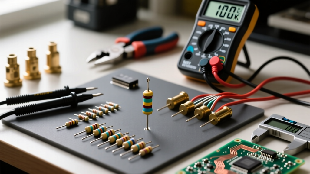
To accurately verify standard 1% resistor values, particularly those below 1kΩ, you must eliminate lead and contact resistance from the equation. This is achieved through 4-wire Kelvin sensing. As detailed in Keysight's basics of resistance measurement, the Kelvin method separates the current-carrying paths from the voltage-sensing paths.
The Kelvin Protocol
- Force Lines (Source): A known, highly stable constant current is forced through the resistor via the outer pair of test leads.
- Sense Lines (Measure): A high-impedance voltmeter measures the voltage drop across the resistor via an inner pair of leads connected as close to the resistor body as possible.
- The Result: Because the sense lines draw virtually zero current (due to the DMM's high input impedance, typically >10 GΩ), there is no voltage drop across the sense leads or the probe contact points. Ohm's Law (R = V/I) is then applied using only the pure voltage drop across the component.
For bench prototyping, utilizing a 6.5-digit bench DMM (such as the Keysight 34461A) paired with Kelvin clips is the minimum requirement for certifying 1% and 0.1% tolerance components.
Environmental Variables: TCR and Soldering Stress
Even with a perfect 4-wire measurement setup, you may find that a 1% resistor measures outside its tolerance band once installed on a PCB. This is rarely a counterfeit component issue; it is a failure to account for environmental coefficients.
Temperature Coefficient of Resistance (TCR)
TCR dictates how much a resistor's value shifts as its temperature changes, measured in parts per million per degree Celsius (ppm/°C). A standard thick-film 1% resistor might have a TCR of ±100 ppm/°C. If your circuit operates in an enclosure that reaches 45°C (a 20°C rise above the 25°C room temperature where you measured it), a 10.00 kΩ resistor will shift by:
Shift = 10,000Ω × (100 × 10^-6) × 20°C = 20Ω
A 20Ω shift on a 10kΩ resistor is a 0.2% change. If the resistor was already sitting at the +0.9% edge of its tolerance band at room temperature, the thermal shift will push it to +1.1%, causing your circuit to fail specification in the field. For high-precision analog front-ends, specifying thin-film resistors with a TCR of ±10 ppm/°C or better is mandatory.
Soldering Heat Shock
The physical act of soldering introduces severe thermal and mechanical stress. The rapid heating and cooling of the resistive element and the ceramic substrate can cause micro-cracking or permanent structural shifts in the resistive film. According to military and aerospace specifications (such as MIL-PRF-55342), a precision resistor is allowed a permanent resistance shift of up to 0.5% after soldering. Always measure critical precision resistors after they have been soldered and allowed to cool to room temperature, never before.
Troubleshooting Out-of-Spec Readings on the Bench
When your verified E96 resistors consistently read outside the 1% band, follow this diagnostic framework before scrapping the batch:
- Verify the Meter's Calibration: Check the DMM's calibration sticker. If it is a budget bench meter, verify its short-term stability by measuring a known, hermetically sealed precision reference resistor (e.g., a Vishay bulk metal foil standard).
- Check for Moisture Absorption: Thick-film resistors are mildly hygroscopic. If your components have been sitting in an unsealed bin in a humid workshop, the substrate may have absorbed moisture, altering the dielectric properties and shifting the resistance. Bake the components at 60°C for two hours and re-measure.
- Inspect for Parallel Leakage Paths: If measuring a high-value precision resistor (e.g., 10 MΩ feedback resistor in a transimpedance amplifier), flux residue on the PCB can create a parallel leakage path. A 10 MΩ resistor in parallel with 50 MΩ of flux residue will measure at roughly 8.33 MΩ—an apparent 16% failure that is actually a contamination issue. Clean the board with high-purity isopropyl alcohol and an ESD-safe brush.
- Evaluate Voltage Coefficient of Resistance (VCR): In high-voltage applications, the resistance value can drop as the applied voltage increases. Ensure your measurement voltage matches the operational voltage of the circuit if VCR is a known factor in your chosen resistor topology.
Conclusion: Respecting the Tolerance Band
Mastering the testing and measurement of standard 1% resistor values requires moving beyond the simplistic view of components as ideal, static numbers. By understanding the logarithmic spacing of the E96 series, acknowledging the inherent limitations of 2-wire DMM measurements, and accounting for the invisible forces of TCR and soldering stress, you elevate your prototyping from guesswork to true engineering. For further reading on practical measurement techniques, Fluke's guide on resistance measurement provides an excellent baseline for maintaining your test equipment and ensuring your bench setups are optimized for precision diagnostics.