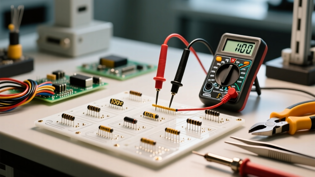

Every electronics workbench has a disorganized bin of standard components, but identifying and verifying common resistor values requires far more nuance than simply reading color bands or silk-screened SMD codes. From a testing and measurement perspective, a 10kΩ pull-up resistor or a 330Ω LED current limiter is not just a static number; it is a dynamic component subject to thermal drift, parasitic parallel paths, and measurement instrument errors.
Whether you are debugging a noisy analog-to-digital converter (ADC) reference or verifying the shunt resistors on a custom power supply, understanding how to properly test these ubiquitous values is a fundamental diagnostic skill. This guide explores the metrology behind standard resistor testing, highlighting the hidden errors that plague standard multimeter measurements and providing actionable protocols for accurate verification.
The Metrology of the E-Series: Why We Test Specific Values
Before diving into measurement techniques, it is crucial to understand why certain values dominate our component kits. The electronics industry relies on the IEC 60063 E-series standard to define preferred numbers. The E12 series (10% tolerance) and E24 series (5% tolerance) establish logarithmic steps, resulting in the ubiquitous values we test daily: 10, 12, 15, 18, 22, 27, 33, 39, 47, 56, 68, and 82.
Multiples of these base numbers—specifically 330Ω, 4.7kΩ, 10kΩ, and 100kΩ—account for the vast majority of resistors found in digital logic and analog signal conditioning. When testing these common resistor values, you must first establish the baseline tolerance. A 5% 4.7kΩ resistor can legally measure anywhere between 4,465Ω and 4,935Ω. If your diagnostic expectation assumes a perfect 4,700Ω, you will misdiagnose perfectly functional circuits as faulty. Always calculate the acceptable tolerance window before applying test probes.
The Test Lead Resistance Trap in Low-Ohm Measurements
One of the most frequent measurement errors occurs when testing low-value common resistors, such as 1Ω, 10Ω, or 47Ω current-limiting resistors used in power paths or inrush protection. A standard digital multimeter (DMM) measures resistance by sourcing a known constant current and measuring the resulting voltage drop. However, the test leads themselves possess inherent resistance.
Engineer's Field Note: A typical pair of 3-foot DMM test leads has a combined resistance of 0.2Ω to 0.5Ω, depending on wire gauge and probe contact quality. If you are testing a common 10Ω shunt resistor with a 5% tolerance (acceptable range: 9.5Ω to 10.5Ω), a 0.4Ω lead resistance introduces a 4% measurement error. You might reject a perfectly good component or, worse, fail to detect a drifted resistor.
The Solution: For any common resistor value below 100Ω, you must use the relative (REL) or zero-null function on your DMM. Short the probe tips together, allow the reading to stabilize, and press the REL button to subtract the lead resistance from subsequent measurements. For mission-critical low-ohm shunts (e.g., 0.1Ω current sense resistors), standard 2-wire DMM testing is entirely inadequate; you must upgrade to 4-wire Kelvin measurement to separate the current-forcing leads from the voltage-sensing leads, eliminating lead resistance from the equation entirely.
In-Circuit Verification: The Parallel Resistance Trap
Testing common resistor values while they remain soldered to a printed circuit board (PCB) is a standard troubleshooting practice, but it is fraught with parallel path errors. Ohm's law dictates that resistors in parallel yield a total resistance lower than the lowest individual resistor in the network.
Case Study: The 10kΩ I2C Pull-Up Resistor
The 10kΩ resistor is arguably the most common pull-up value in digital electronics, frequently used on I2C bus lines (SDA and SCL). If you place your DMM probes across a 10kΩ pull-up resistor on an unpowered I2C bus, you will rarely read 10kΩ. Instead, you might read 4.2kΩ or even lower.
This happens because the DMM's test voltage forward-biases the internal ESD protection diodes of the connected microcontrollers and sensors, or simply measures the parallel impedance of the IC input buffers. To accurately verify a 10kΩ pull-up resistor in-circuit, you must desolder or lift at least one leg of the component to isolate it from the parallel semiconductor junctions. If lifting the leg is impossible, you must rely on functional bus analysis (e.g., checking I2C rise times with an oscilloscope) rather than static resistance measurements.
Thermal Drift: Testing Under Active Load
Resistors change value as they heat up, a phenomenon defined by the Temperature Coefficient of Resistance (TCR), usually expressed in parts per million per degree Celsius (ppm/°C). While a standard 1/4W metal film resistor might have a TCR of ±50 ppm/°C, carbon composition resistors or thick-film SMD resistors can exhibit significantly higher thermal drift.
Consider a common 220Ω LED current-limiting resistor dissipating 100mW in a cramped, unventilated enclosure. The localized temperature rise can easily exceed 40°C above ambient. If the resistor has a TCR of +500 ppm/°C, a 40°C rise will cause a 2% positive drift in resistance. While a 2% shift in LED brightness is imperceptible to the human eye, a similar thermal drift in a 100kΩ op-amp feedback resistor will catastrophically alter the gain and offset of a precision amplifier.
Active Thermal Testing Protocol
- Baseline Measurement: Measure the resistor at room temperature (25°C) using a precision DMM.
- Apply Load: Power the circuit or inject a controlled current to bring the resistor to its nominal operating temperature.
- Thermal Stabilization: Wait 3 to 5 minutes for the thermal mass to stabilize.
- Hot Measurement: Measure the voltage drop across the resistor and the current through it simultaneously. Calculate the hot resistance using Ohm's Law (R = V / I). Do not use a standard DMM ohms range on a live circuit.
High-Impedance Errors: Testing 1MΩ and Above
Common high-value resistors, such as 1MΩ, 2.2MΩ, and 10MΩ, are frequently used in high-voltage divider networks, electrometer front-ends, and timing circuits. Testing these values introduces a new set of instrument limitations.
Standard DMMs have an input impedance of 10MΩ on their voltage ranges, but their resistance measurement circuitry can struggle with high-impedance nodes due to surface leakage currents on the PCB and the DMM's own input bias currents. Furthermore, handling a 10MΩ resistor with bare fingers during testing will introduce parallel skin resistance, which can range from 500kΩ to several megaohms depending on skin moisture, severely skewing the measurement. Always use insulated tweezers or a dedicated component test fixture when verifying high-value common resistors.
Reference Chart: Testing Protocols for Common Resistor Values
The following table outlines the optimal testing methodology for the most frequently encountered standard resistor values in DIY and commercial prototyping.
| Common Value | Typical Application | Nominal Tolerance | Max Acceptable Deviation | Required Measurement Protocol |
|---|---|---|---|---|
| 0.1Ω | Current Shunt / Sense | 1% | ±0.001Ω | 4-Wire Kelvin Micro-ohm Meter |
| 10Ω | Gate Drive / Inrush | 1% | ±0.1Ω | DMM with REL (Zero) Nulling |
| 330Ω | LED Current Limiting | 5% | ±16.5Ω | Standard 2-Wire DMM |
| 4.7kΩ | I2C Pull-Up | 1% | ±47Ω | Out-of-Circuit DMM Measurement |
| 10kΩ | GPIO Pull-Up/Down | 5% | ±500Ω | Out-of-Circuit DMM Measurement |
| 100kΩ | Op-Amp Feedback | 1% | ±1kΩ | Precision DMM (No Skin Contact) |
| 10MΩ | HV Divider / Timing | 1% | ±100kΩ | Insulated Fixture / Guard Rings |
Conclusion: Moving Beyond the Color Code
Testing common resistor values is an exercise in applied metrology. While the E-series standard gives us a predictable palette of components, the physical realities of test lead resistance, parallel circuit paths, and thermal drift dictate that a simple color-code reading is never enough for critical diagnostics. By adopting relative-null measurements for low-ohm shunts, isolating pull-up resistors from semiconductor junctions, and calculating active thermal drift, you elevate your troubleshooting from basic component checking to true circuit-level engineering analysis. For deeper dives into precision measurement techniques, consult application notes from Tektronix and ensure your test equipment is regularly calibrated against known reference standards.