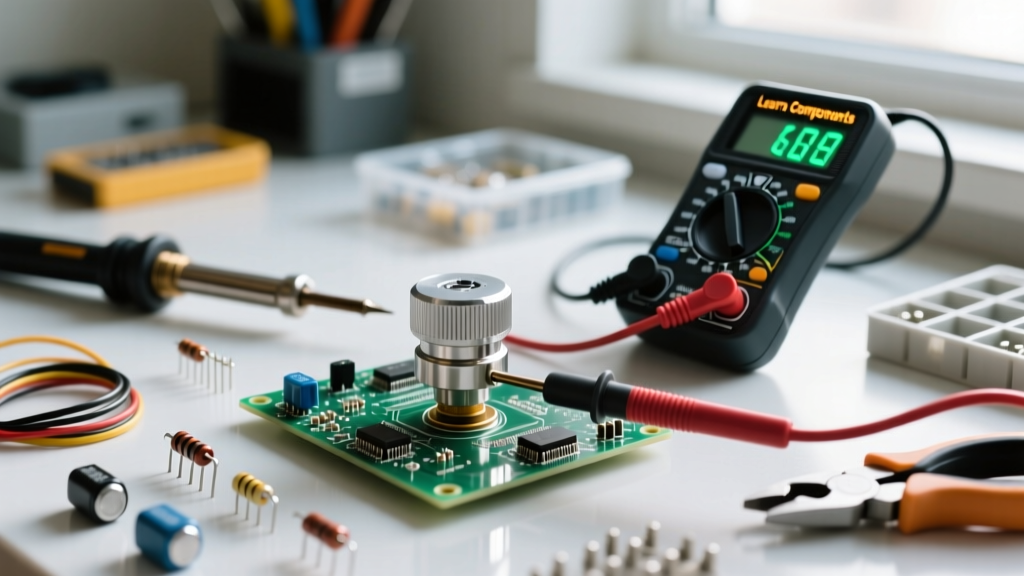

The Anatomy of Potentiometer Terminals
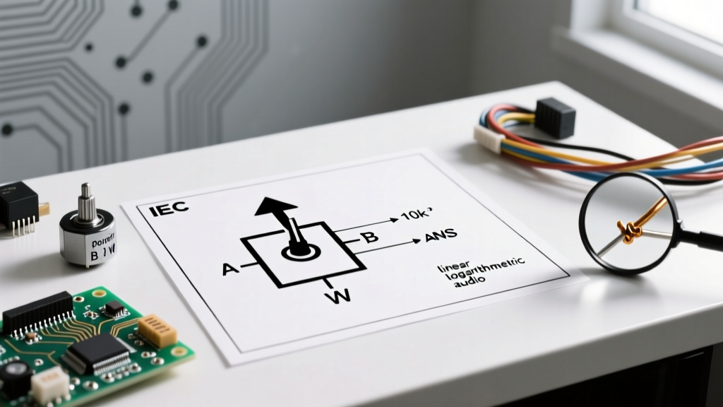
A standard rotary or slide potentiometer relies on a resistive track and a movable wiper. To accurately perform potentiometer testing, you must first identify the three external lugs. While manufacturer datasheets vary, the industry-standard pinout for a front-facing rotary pot (like the ubiquitous Alpha 16mm or Bourns PTV series) is:
- Terminal 1 (CCW): Counter-clockwise end of the resistive track.
- Terminal 2 (Wiper): The movable contact that sweeps across the track.
- Terminal 3 (CW): Clockwise end of the resistive track.
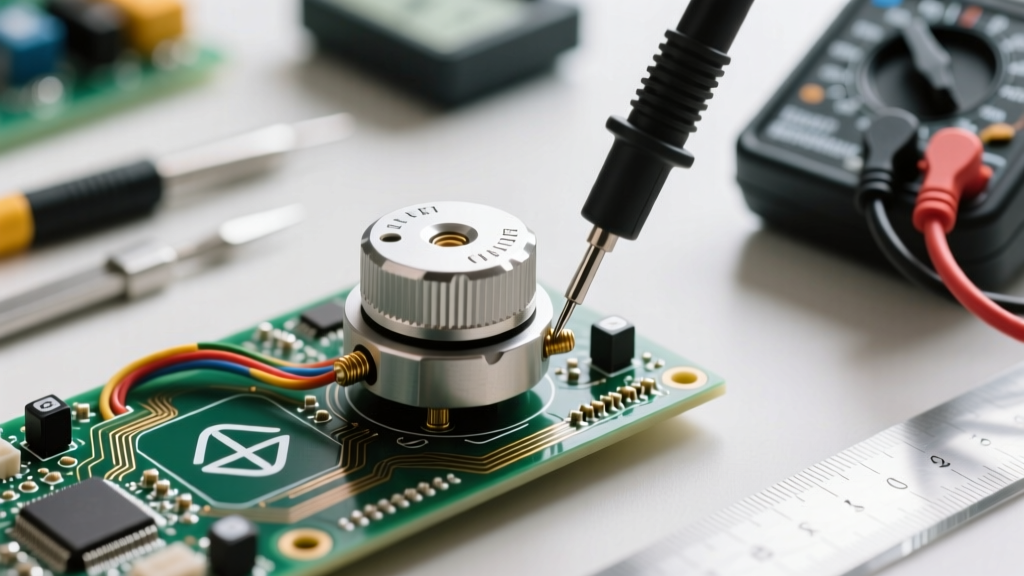
If you are testing a surface-mount trimpot, such as the Bourns 3296W multi-turn cermet potentiometer, the pinout is typically printed on the top shield, with the center pin acting as the wiper. Misidentifying the wiper is the most common cause of erratic measurement readings during prototyping.
Essential Tools for Precision Measurement
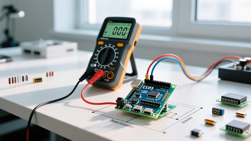
While any basic DMM can check for continuity, diagnosing subtle wiper noise or taper anomalies requires a meter with high resolution and fast sampling rates. A true-RMS meter like the Fluke 117 or the Brymen BM235 is ideal. Additionally, you will need:
- Fine-tipped alligator clips or SMD grabbers (to prevent hand-induced resistance fluctuations).
- A non-conductive adjustment tool (for multi-turn trimpots).
- Isopropyl alcohol (99%) and contact cleaner (e.g., DeoxIT D5) for rehabilitation.
Step-by-Step Potentiometer Measurement Guide
Effective testing requires isolating the component from the active circuit. Desolder at least one terminal (preferably the wiper) to prevent parallel circuit paths from skewing your ohmmeter readings.
1. Measuring Total Nominal Resistance
Set your DMM to the appropriate resistance range. Place the probes across Terminal 1 and Terminal 3. The reading should match the nominal resistance printed on the casing (e.g., 10kΩ, 50kΩ, 100kΩ) within the manufacturer's specified tolerance, typically ±10% or ±20% for carbon track pots, and ±1% for precision wirewound models.
Expert Insight: If your reading fluctuates wildly while the shaft is stationary, the internal resistive element is likely cracked or severely oxidized. Carbon composition pots are highly susceptible to moisture ingress, which alters the bulk resistance over time.
2. Verifying the Taper (Linear vs. Audio)
The taper defines how resistance changes relative to shaft rotation. This is critical in audio volume controls and sensor scaling. Leave the DMM connected to Terminal 1 and Terminal 2 (the wiper).
- Linear Taper (B-Taper): At the exact mechanical midpoint (50% rotation), the resistance between Pin 1 and Pin 2 should be exactly 50% of the total resistance.
- Audio/Logarithmic Taper (A-Taper): At the 50% mechanical rotation point, the resistance between Pin 1 and Pin 2 will typically measure around 10% to 15% of the total resistance, compensating for the human ear's logarithmic perception of loudness.
Rotate the shaft slowly. The resistance should climb smoothly. Any sudden drops to zero or spikes to infinity indicate a 'dead spot' on the resistive track.
3. Dynamic Wiper Noise and Contact Resistance
Wiper contact resistance is the parasitic resistance between the movable metal contact and the resistive track. To measure this dynamically, connect your DMM probes to the wiper (Terminal 2) and the track terminal it is currently closest to. Set the meter to its lowest ohms range (or millivolts if injecting a test current). Slowly rotate the shaft through its entire travel. A healthy cermet or conductive plastic pot will show a contact resistance of less than 50 milliohms. Older carbon pots may exhibit 1 to 5 ohms of contact resistance, which can introduce significant thermal noise in high-gain audio preamps.
Potentiometer Failure Modes and Diagnostic Table
Understanding how specific materials fail helps you decide whether to clean, recalibrate, or replace the component. Below is a diagnostic matrix based on common bench failures.
| Failure Mode | Primary Cause | DMM Symptom (Wiper to Track) | Recommended Action |
|---|---|---|---|
| Dead Spots | Physical wear of carbon track | Infinite resistance (OL) at specific angles | Replace immediately |
| Wiper Oxidation | Environmental sulfur/moisture | Fluctuating resistance (10Ω - 1kΩ) | Clean with DeoxIT D5 |
| Track Delamination | Overheating / Excessive wiper current | Permanent open circuit across all pins | Replace and review circuit current |
| Mechanical Slip | Worn D-shaft or loose collet | Resistance stops changing before physical end-stop | Replace hardware |
Advanced Diagnostics: Oscilloscopes and Signal Tracing
For high-fidelity audio or precision servo feedback loops, a multimeter is insufficient to capture microsecond wiper bounce. Inject a clean 1kHz sine wave or a 5V DC reference across Terminals 1 and 3. Connect an oscilloscope probe to the wiper (Terminal 2). As you rotate the shaft, the waveform amplitude should scale smoothly. If you observe high-frequency 'fuzz' or momentary dropouts on the oscilloscope trace, you are witnessing wiper bounce—a phenomenon where the mechanical contact momentarily lifts off the track due to microscopic debris or track unevenness. In digital control applications, this bounce can cause microcontrollers to register erratic ADC values, necessitating software debouncing or hardware RC filtering.
Rehabilitation: When to Clean and When to Replace
Not all scratchy or erratic potentiometers belong in the trash. High-end audio equipment often utilizes sealed, precision conductive plastic pots (like the ALPS RK27 series) that can be rehabilitated.
For open-frame carbon pots, apply a single drop of CAIG DeoxIT D5 directly onto the track and sweep the wiper back and forth 20 times. This dissolves oxides and leaves a protective anti-oxidant film. Never use standard WD-40 or harsh solvents, as these will dissolve the carbon binder and permanently ruin the resistive element. If the pot is a sealed multi-turn trimpot (e.g., Bourns 3386 series) exhibiting internal noise, cleaning is impossible; desoldering and replacement is the only viable path.
By mastering these measurement techniques, you can confidently diagnose circuit anomalies, verify component tapers before soldering, and rescue vintage electronics from the scrap heap. For deeper insights into component tolerances and material science, refer to the Bourns Technical Library and the foundational guides on passive components at Electronics Tutorials.