
The Project Scenario: Resurrecting a Dead 24-Inch LCD Monitor
Welcome back to the workbench. Today’s project-based learning module focuses on a classic electronics repair scenario: a 24-inch Dell LCD monitor that exhibits the 'click of death.' When you press the power button, you hear a faint relay click, the power LED flashes briefly, and the screen remains black. In the world of consumer electronics repair, this symptom almost universally points to a failing switched-mode power supply (SMPS) board. Specifically, the low-voltage DC filter capacitors on the 5V and 12V rails have degraded, causing the power management IC to trigger an under-voltage lockout.
Rather than blindly replacing every component or throwing the board in the e-waste bin, we are going to systematically diagnose the fault. Learning how to test capacitor components accurately is a foundational skill for any DIY electronics enthusiast or professional repair technician. By the end of this project, you will understand the physics of capacitor degradation, the limitations of standard multimeters, and the precise methodology for verifying component health using advanced diagnostic tools.
Visual Triage: Spotting the Usual Suspects Before Testing
Before we apply any probes or heat to the board, we must perform a visual inspection. Electrolytic capacitors are essentially tiny cans filled with a liquid or gel electrolyte and a rolled-up sheet of aluminum foil. When subjected to excessive heat, ripple current, or poor manufacturing chemistry (reminiscent of the infamous 'capacitor plague' of the early 2000s), the electrolyte breaks down and generates internal gas.
The 'Dome and Leak' Failure Modes
Examine the tops of the cylindrical capacitors on the secondary side of the power board. Manufacturers score the aluminum casing with a 'K' or cross pattern to act as a pressure relief vent. If you observe any of the following, the capacitor has suffered catastrophic mechanical failure and must be replaced immediately:
- Bulging/Doming: The top of the capacitor is convex rather than perfectly flat.
- Venting: The scored 'K' pattern has split open, often accompanied by a crusty brown or black residue.
- Sleeve Shrinkage: The plastic insulation sleeve is melted, cracked, or pulled away from the base, indicating severe thermal stress from adjacent components.
- Seep Leakage: Electrolyte has leaked out of the bottom rubber bung, corroding the copper traces on the PCB.
However, visual inspection only catches about 30% of failed capacitors. The most insidious failure mode—dielectric drying and increased Equivalent Series Resistance (ESR)—leaves the component looking perfectly pristine. To find these silent killers, we must move to electrical testing.
Gear Up: Tools Required for Deep Component Diagnostics
A common beginner mistake is attempting to diagnose capacitor health using only the capacitance setting on a standard digital multimeter (DMM). While a high-end DMM like the Fluke 117 is invaluable for checking voltage rails and continuity, its capacitance function is largely useless for finding degraded power supply filters. A capacitor might read 980µF on a DMM (well within the ±20% tolerance of a 1000µF cap) but still possess an ESR so high that it acts like a resistor, filtering out high-frequency switching noise and causing system instability.
To properly execute this project, you need two specialized tools:
- An ESR Meter (e.g., MESR-100 V2 or Atlas ESR70): This device injects a high-frequency AC signal (typically 100kHz) into the component to measure its internal resistance without being affected by the capacitance value. Crucially, good ESR meters allow for in-circuit testing.
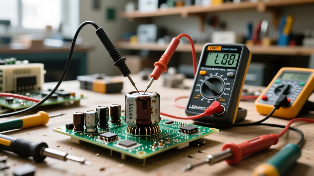
- An LCR Meter (e.g., DER EE DE-5000): Used for out-of-circuit verification, measuring exact capacitance (C), dissipation factor (D), and leakage current at various test frequencies.
Safety First: The Art of the Safe Discharge
Critical Safety Warning: The primary side of an SMPS board contains large bulk filter capacitors that can hold lethal DC voltages (up to 400V) long after the device is unplugged. Never touch the primary side traces or capacitor legs without verifying they are discharged.
Do not use the 'screwdriver spark' method to discharge capacitors. Shorting a charged capacitor with a metal tool causes a massive instantaneous current spike that can vaporize the screwdriver tip, damage your eyes with shrapnel, and destroy the capacitor's internal foil connections. Instead, build a simple discharge tool: solder a 100-ohm, 5-watt power resistor to two insulated probe leads. Clamp the leads across the capacitor terminals for 5 to 10 seconds to safely bleed off the stored energy as heat.
Step-by-Step: How to Test Capacitor Health In-Circuit
Desoldering every capacitor on a board to test it is a massive waste of time and risks lifting the delicate copper pads on the PCB. Thanks to the high-frequency AC signal used by ESR meters, we can test components while they are still soldered to the board. The surrounding silicon diodes and transformer windings present a high impedance at 100kHz, effectively isolating the capacitor for the brief duration of the test.
Phase 1: The Quick In-Circuit ESR Check
Power on your MESR-100 ESR meter and short the probe tips together to zero out the lead resistance. Locate the 1000µF 16V and 2200µF 10V filter capacitors on the secondary side of our salvaged LCD power board. Press the probe tips firmly against the solder joints on the underside of the PCB.
If the 1000µF capacitor yields an ESR reading of 0.04 ohms, it is in excellent health. If the meter reads 2.8 ohms or displays 'Out of Range,' the electrolyte has dried out, and the component is the root cause of our monitor's failure. Mark the top of any failing capacitors with a silver paint pen or Sharpie for easy identification during the desoldering phase.
Phase 2: Out-of-Circuit Capacitance and Leakage Verification
Once the faulty capacitors are desoldered, we move to the LCR meter for a forensic breakdown. According to the Cornell Dubilier Application Guide, electrolytic capacitors suffer from a gradual loss of capacitance over time as the electrolyte evaporates through the rubber end seal. Set your LCR meter to 120Hz (the standard test frequency for bulk filter caps) and measure the capacitance. A reading below 80% of the rated value confirms severe degradation. Furthermore, testing the Dissipation Factor (D) will reveal the dielectric losses that a simple DMM completely misses.
Data Matrix: Interpreting Your Multimeter and ESR Readings
Having a reference matrix at your workbench is critical for making rapid pass/fail decisions. The table below outlines acceptable ESR thresholds for common through-hole electrolytic capacitors measured at 100kHz. For deeper community insights on specific brand failure rates, the BadCaps.net repair forums remain an invaluable resource for cross-referencing manufacturer batch codes.
| Capacitance Rating | Voltage Rating | Excellent ESR (< Ω) | Marginal ESR (Ω) | Failed ESR (> Ω) |
|---|---|---|---|---|
| 470µF | 16V / 25V | < 0.10 | 0.11 - 0.30 | > 0.50 |
| 1000µF | 10V / 16V | < 0.05 | 0.06 - 0.15 | > 0.25 |
| 2200µF | 10V / 16V | < 0.03 | 0.04 - 0.10 | > 0.15 |
| 3300µF | 6.3V / 10V | < 0.02 | 0.03 - 0.08 | > 0.12 |
| 47µF | 50V | < 0.80 | 0.81 - 2.00 | > 3.50 |
Note: Always consult the specific manufacturer's datasheet (e.g., Rubycon, Nichicon, Panasonic) for exact ESR specifications, as 'Low-ESR' and 'Ultra-Low-ESR' series components will have significantly tighter tolerances than standard general-purpose capacitors.
Project Wrap-Up: Soldering Replacements and Power-On Testing
With the faulty components identified and removed, it is time to source replacements. Never replace a power supply filter capacitor with a standard, general-purpose 85°C capacitor. You must use Low-ESR, 105°C rated components designed for high-ripple current applications. Excellent choices include the Panasonic FR series, Rubycon ZL series, or Nichicon PW series. For comprehensive testing methodologies and tool calibration, Fluke's guide on testing capacitors provides excellent baseline safety protocols for bench work.
Because modern consumer electronics utilize RoHS-compliant lead-free solder, your soldering iron must be set to a higher temperature profile—typically between 350°C and 380°C. Apply a small amount of fresh 63/37 leaded flux-core solder to the old joints to lower the melting point of the factory solder, then use a desoldering pump or braided copper wick to clear the through-holes. Insert the new capacitors, paying strict attention to the polarity stripe on the sleeve and the corresponding shaded silkscreen on the PCB. Reversing the polarity of an electrolytic capacitor will result in a violent explosion when power is applied.
Once the board is cleaned with isopropyl alcohol and visually inspected for solder bridges, reinstall it into the LCD monitor chassis. Plug in the IEC cable, press the power button, and watch the backlight illuminate. By mastering the science of ESR and moving beyond basic visual checks, you have successfully rescued a piece of hardware from the landfill, saved the cost of a replacement, and leveled up your component-level diagnostic skills.