
The Procurement Gap: When Schematic Symbols Cause BOM Errors
In hardware development, the transition from ECAD design to physical manufacturing is fraught with translation errors. For procurement specialists and inventory managers, understanding the exact schematic symbol for a potentiometer is not just an exercise in electrical theory; it is a critical supply chain safeguard. A generic resistor symbol with an arrow might represent a $0.10 single-turn carbon film trimmer, or it might represent a $15.00 precision multi-turn conductive plastic servo potentiometer. When design engineers rely on default, unverified schematic library parts, the resulting Bill of Materials (BOM) often lacks the mechanical and electrical nuances required for accurate sourcing.
This misalignment leads to severe inventory bloat, assembly line stoppages, and field failures. If a buyer sources a linear taper potentiometer because the schematic lacked the specific logarithmic taper notation, an audio mixer will exhibit a highly non-linear, unusable volume curve. By bridging the gap between schematic symbology and component distribution catalogs like Digi-Key or Mouser, hardware teams can drastically reduce procurement errors and optimize their electromechanical inventory.
Standard IEC vs. ANSI: Identifying the Base Symbol
The foundational shape of the potentiometer symbol depends on the regional standard adopted by the engineering team. The International Electrotechnical Commission (IEC) standard depicts the resistive element as a solid rectangle. Conversely, the American National Standards Institute (ANSI) standard represents the resistive track as a zigzag line. From a sourcing perspective, the shape itself does not dictate the Manufacturer Part Number (MPN). However, the standard used often correlates with the pinout conventions the designer expects.
The Arrow and the Zigzag: Terminal 1, 2, and 3 Mapping
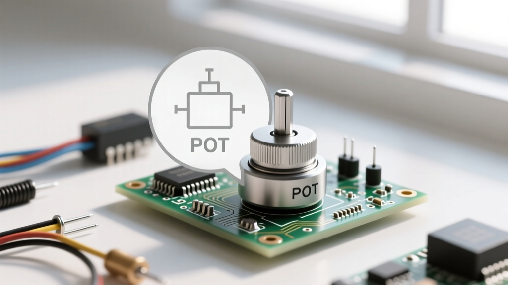
The defining feature of any potentiometer symbol is the wiper, represented by an arrow pointing at the resistive element. In a standard three-terminal configuration, the terminals are mapped as follows:
- Terminal 1 (CCW): The counter-clockwise end of the resistive track.
- Terminal 2 (Wiper): The moving contact (the arrow in the symbol).
- Terminal 3 (CW): The clockwise end of the resistive track.
Procurement teams must verify that the physical footprint matches the schematic pinout. Reversing Terminal 1 and Terminal 3 in the schematic does not destroy the circuit, but it reverses the physical rotation direction of the knob. In consumer electronics or industrial control panels, a 'reverse-acting' volume or speed control results in immediate user rejection and costly field returns. Always cross-reference the symbol's pinout with the manufacturer's datasheet before locking in the BOM.
Taper Symbols and Inventory Implications (Linear vs. Logarithmic)
The 'taper' defines how the resistance changes relative to the shaft's physical rotation. This is where schematic symbols cause the most frequent sourcing disasters. According to Digi-Key's technical guide on potentiometer basics, tapers are generally categorized into Linear (B), Logarithmic/Audio (A), and Anti-Logarithmic (C).
In many European and Asian schematic standards, a straight diagonal line drawn next to the potentiometer symbol indicates a Linear taper, while a curved line indicates a Logarithmic taper. However, in older US schematics, these notations were sometimes omitted entirely, leaving the taper to be defined only by a comment text block.
The Inventory Impact: Linear (B-taper) cermet and carbon pots are high-volume, off-the-shelf commodities with minimal lead times. Logarithmic (A-taper) pots, essential for audio applications, require specialized resistive ink deposition. Sourcing an A-taper part, such as the Alps Alpine RK09K series, often involves higher Minimum Order Quantities (MOQs) and longer factory lead times compared to standard B-taper equivalents. If the schematic symbol lacks a clear taper indicator, buyers default to the cheapest linear option, silently sabotaging the product's audio performance.
Rheostat Configurations: Spotting the Two-Terminal Symbol
Frequently, a potentiometer is used as a variable resistor (rheostat) rather than a voltage divider. The schematic symbol for a potentiometer wired as a rheostat shows the wiper (Terminal 2) physically tied to either Terminal 1 or Terminal 3.
Why does this matter for sourcing? First, it dictates the power rating required. A voltage divider handles minimal current, but a rheostat must dissipate the full load current as heat. If a designer draws a rheostat symbol but specifies a standard 0.2W carbon track pot in the BOM, the component will overheat and fail. Procurement must recognize the rheostat symbol and source higher-wattage wirewound or robust cermet alternatives, such as the Vishay 534 series, ensuring the inventory reflects the actual thermal demands of the circuit.
Trimmer vs. Panel Mount: Visual Cues for Purchasing
Schematic symbols often differentiate between user-facing panel potentiometers and PCB-mounted calibration trimmers (trimpots). A trimmer symbol is frequently enclosed in a box, or the wiper arrow is replaced with a symbol resembling a screwdriver slot or a gear.
Recognizing this distinction is vital for packaging and assembly logistics. Panel mount pots (like the Bourns PTV09A series) are sourced in bulk trays or individual bags and require manual soldering or panel integration. Trimpots, such as the ubiquitous Bourns 3296W multi-turn trimmer, are often sourced in tape-and-reel or tube packaging for automated wave soldering. Misinterpreting a trimmer symbol as a panel pot can result in purchasing components with the wrong lead terminations (e.g., right-angle PC pins vs. long solder lugs), halting the SMT assembly line.
Multi-Gang and Switched Potentiometer Symbols
Complex audio and instrumentation designs utilize multi-gang potentiometers (two or more resistive tracks on a single shaft) or switched potentiometers (a pot with an integrated pull-switch). The schematic symbol for a multi-gang pot displays multiple resistor symbols connected by a dashed mechanical line, indicating they share a single physical shaft. Switched pots include a standard SPST or DPST switch symbol mechanically linked to the wiper.
Sourcing Trap: If a junior buyer misses the dashed mechanical link line, they may source two separate single-gang potentiometers instead of one dual-gang unit (like the ALPS RK27 series). This not only doubles the BOM cost and PCB footprint but renders the physical assembly impossible. Always audit the schematic for mechanical linkage lines before finalizing the MPN.
BOM Translation Table: Symbol to MPN Sourcing Guide
The following table serves as a quick-reference framework for procurement teams translating schematic visual cues into specific component categories and sourcing strategies.
| Schematic Visual Cue | Component Category | Example MPN / Series | Sourcing & Inventory Strategy |
|---|---|---|---|
| Zigzag/Rectangle + Standard Arrow | Standard Panel Pot (Linear) | Bourns PTV09A-4015F-B103 | High availability; source locally to minimize freight costs on bulky items. |
| Curved Line Notation ('A' Taper) | Audio Panel Pot (Logarithmic) | Alps Alpine RK09K1110B1R | Longer lead times; maintain safety stock due to specialized manufacturing. |
| Boxed Symbol / Screwdriver Slot | PCB Trimmer (Single Turn) | Bourns 3362P-1-103LF | Order in tape-and-reel for automated insertion; verify cermet vs. carbon. |
| Boxed Symbol + Multiple Arrows | Multi-Turn Trimmer | Bourns 3296W-1-103LF | High precision; verify top-adjust vs. side-adjust footprint before ordering. |
| Dashed Line Linking Two Symbols | Dual-Gang Potentiometer | ALPS RK2711120B1C | Strict MOQ constraints; consolidate orders to avoid per-unit surcharges. |
| Wiper Tied to End Terminal | Rheostat (Variable Resistor) | Vishay 534B1103JC | Check wattage ratings; standard 0.5W pots will burn out in power circuits. |
Vendor Strategies: Managing Potentiometer Lead Times
The global supply chain for electromechanical components is highly sensitive to raw material fluctuations, particularly regarding copper alloys for wipers and specialized resistive inks. When auditing a BOM based on schematic symbols, procurement professionals should consult resources like Bourns' official potentiometer portfolio or Vishay's Potentiometer FAQ and application notes to understand the lifecycle status of specific resistive elements.
Carbon composition potentiometers are increasingly facing obsolescence due to poor environmental stability and wear. If a legacy schematic specifies a carbon track pot, buyers should proactively initiate an Engineering Change Order (ECO) to swap the MPN to a modern cermet or conductive plastic equivalent. Cermet (ceramic-metal) trimmers offer superior temperature stability and longer rotational life, making them the preferred choice for industrial inventory planning. By standardizing the CAD library to only include modern, highly-available cermet and conductive plastic MPNs, companies can insulate themselves from sudden end-of-life (EOL) notices.
Conclusion: Standardizing Library Parts for Smoother Procurement
The schematic symbol for a potentiometer is the very first link in the hardware supply chain. When ECAD libraries are poorly maintained, relying on generic symbols devoid of taper, mechanical, and packaging metadata, the burden of interpretation falls on the procurement team. This inevitably leads to BOM mismatches, incorrect physical footprints, and delayed product launches.
To achieve sourcing excellence, hardware organizations must enforce strict CAD library governance. Every potentiometer symbol must be intrinsically linked to a verified MPN, complete with datasheets detailing the exact taper curve, mechanical life cycle, and termination style. By treating the schematic symbol not just as a drawing, but as a direct procurement directive, engineering and supply chain teams can collaborate seamlessly, ensuring that the components on the warehouse shelf perfectly match the vision on the schematic.