
For any electronics hobbyist or professional prototyping lab, the humble relay module is a foundational building block. Whether you are switching a 120V AC mains load for a smart home project or controlling a high-current DC motor for robotics, these modules bridge the gap between low-voltage microcontrollers and high-power loads. However, the market is flooded with variations of varying quality, making sourcing and inventory management a surprising challenge. In this guide, we will dissect the bill of materials (BOM) of common relay modules, outline strategic sourcing channels, and establish a robust inventory protocol for your lab.
Deconstructing the Generic Relay Module BOM
Before you can effectively source and stock relay modules, you must understand what you are actually buying. The most ubiquitous module on the market is the 1-channel, 5V opto-isolated board featuring the Songle SRD-05VDC-SL-C electromechanical relay. While the relay itself is a known quantity, the supporting circuitry on the PCB dictates the module's real-world reliability.
A standard generic module includes three critical supporting components:
- The Optocoupler: Usually a PC817 or EL817. This provides galvanic isolation between your microcontroller's GPIO pins and the relay's inductive coil.
- The Switching Transistor: Typically an S8050 NPN bipolar junction transistor (BJT) that amplifies the tiny current from the optocoupler's phototransistor to drive the relay coil.
- The Flyback Diode: Placed in parallel with the coil to suppress inductive voltage spikes when the relay switches off.
Information Gain: Many ultra-cheap modules sourced from grey-market vendors use a 1N4148 small-signal diode for flyback protection. While the 1N4148 is fast, its peak forward surge current rating is often insufficient for the massive inductive kickback generated by larger relay coils. When auditing your inventory, look for modules utilizing a 1N4007 or similar rectifier diode, which can safely absorb the transient energy without catastrophic failure.
The Sourcing Divide: Authorized vs. Grey Market
Where you buy your modules fundamentally impacts your project's lifespan. Sourcing can be broadly divided into two categories:
Authorized Distributors (Mouser, Digi-Key, Farnell)
When you source from authorized distributors like Mouser's Electromechanical Relays category, you are typically buying bare, high-quality relays from manufacturers like Omron, Panasonic, or TE Connectivity, alongside professionally manufactured carrier boards. These modules feature genuine optocouplers with guaranteed Current Transfer Ratios (CTR), heavy-duty screw terminals rated for their stated amperage, and proper PCB trace clearances for mains voltage isolation. Expect to pay $4.00 to $8.00 per channel.
Grey Market (AliExpress, Amazon, eBay)
Generic modules from marketplaces often cost between $0.60 and $1.50 per channel. While excellent for low-stakes prototyping, they suffer from inconsistent quality control. The screw terminals may use soft pot-metal that strips easily, and the PCB isolation slots (the physical gap between high and low voltage traces) are often dangerously narrow or missing entirely. If you source from these channels for permanent installations, you must physically inspect the underside of the PCB for adequate clearance routing.
The 3.3V Microcontroller Compatibility Illusion
One of the most common failure modes in DIY prototyping occurs when engineers attempt to use a standard '5V Arduino-compatible' relay module with a 3.3V microcontroller like the ESP32, Raspberry Pi Pico, or STM32.
Most generic modules feature a 1kΩ current-limiting resistor on the input side of the optocoupler's internal IR LED. At 5V logic, this provides roughly 4mA of current—enough to trigger the PC817. However, at 3.3V logic, the current drops below the optocoupler's threshold, resulting in a module that simply will not trigger, or triggers intermittently. When building your inventory, consider sourcing specific '3.3V Logic Level' relay modules, which utilize lower forward-voltage optocouplers or onboard MOSFETs to guarantee reliable switching at lower GPIO voltages.
Strategic Inventory Matrix for the DIY Lab
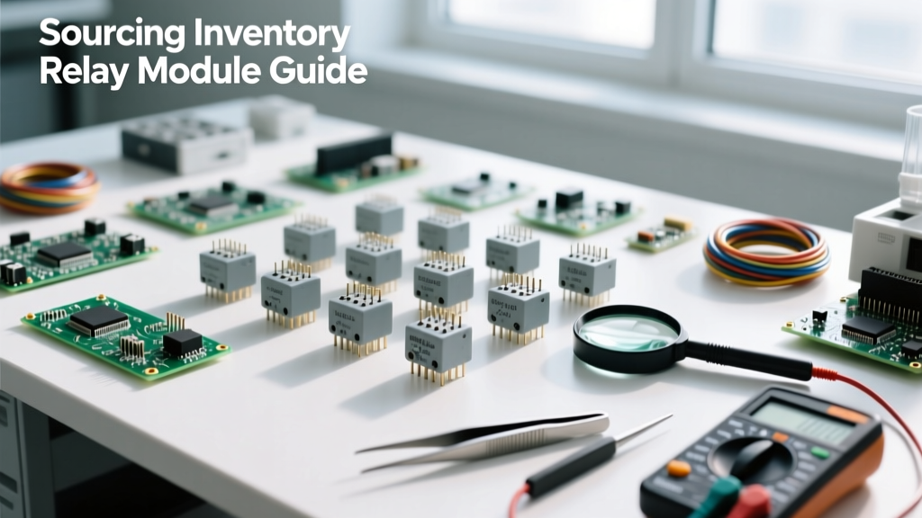
Hoarding random relay modules leads to a disorganized lab and stalled projects. A strategic inventory should be categorized by coil voltage, contact configuration, and load type. Below is a recommended baseline inventory matrix for a well-rounded prototyping lab.
| Module Type | Coil Voltage | Contact Config | Primary Use Case | Recommended Stock |
|---|---|---|---|---|
| Standard Opto-Isolated | 5V DC | SPDT (10A) | Arduino/AVR mains switching, solenoid control | 10 units (1, 2, and 4-channel) |
| Logic-Level Opto | 3.3V DC | SPST-NO (10A) | ESP32/Pi Pico smart home integrations | 5 units |
| Automotive / High Current | 12V DC | SPDT (30A) | Car audio, winch control, high-power DC motors | 3 units (Bosch-style or heavy-duty PCB) |
| Solid State Relay (SSR) | 3-32V DC Input | SPST-NO (2A-25A) | PWM heating control, silent AC switching | 4 units (e.g., Omron G3MB series) |
Storage Protocols and Contact Oxidation
Do relay modules expire? Mechanically, an unused relay has an essentially infinite shelf life. However, the electrical contacts are highly susceptible to environmental degradation. The contacts inside standard electromechanical relays are typically made of silver alloys (like Silver Tin Oxide, AgSnO2). When exposed to high humidity and airborne sulfur or industrial pollutants, these contacts can develop a non-conductive oxide or sulfide layer.
According to application notes from major component manufacturers, this oxidation can lead to high contact resistance or outright failure to pass low-level signals when the relay is finally put into service. To preserve your inventory:
- Moisture Barrier Bags (MBB): Store bare modules in sealed MBBs with silica gel desiccant packets, especially if your lab is in a high-humidity climate.
- Avoid Corrosive Environments: Never store relay inventory in the same drawer or cabinet as bare sulfur-based chemicals, certain types of vulcanized rubber, or harsh fluxes.
- Terminal Protection: For modules with exposed screw terminals, a light coating of dielectric grease on the metal threads can prevent galvanic corrosion over years of storage.
The JD-VCC Jumper: A Sourcing and Usage Warning
Expert Prototyping Tip: Many multi-channel relay modules feature a 'JD-VCC' jumper. If this jumper is in place, the module's logic side shares a ground with the relay coil side, entirely defeating the purpose of the optocoupler. For true galvanic isolation—which protects your expensive microcontroller from mains voltage transients—you must remove the jumper and supply JD-VCC from a completely separate, isolated 5V power source. Always verify the PCB trace routing on cheap modules; some manufacturers mistakenly tie the grounds together on the PCB regardless of the jumper position.
When to Pivot Inventory to Solid State Relay (SSR) Modules
As your projects mature, you will encounter scenarios where mechanical relay modules fail prematurely. Mechanical relays have a finite electrical lifespan (often rated for only 100,000 cycles under load) due to contact arcing and pitting. If you are designing a project that requires rapid switching—such as a PID temperature controller using PWM to drive a heating element—mechanical relays will weld their contacts shut or fail within weeks.
For these applications, your inventory must include Solid State Relay (SSR) modules. SSRs, such as those based on the Omron G3MB-202P chip, use TRIACs or MOSFETs to switch loads with zero moving parts. They offer millions of switching cycles, silent operation, and zero-crossing detection to minimize electromagnetic interference (EMI). While they cost slightly more and require heatsinking for loads above 2 Amps, stocking a few SSR modules is a mandatory evolution for any serious electronics lab. For deeper integration insights, SparkFun's Relay Hookup Guide provides excellent schematics for interfacing both mechanical and solid-state variants safely.
Final Thoughts on Lab Procurement
Sourcing relay modules is not merely about finding the lowest price per channel; it is about understanding the hidden compromises in BOM selection, logic-level compatibility, and isolation routing. By categorizing your inventory by voltage and contact type, enforcing strict moisture-controlled storage, and knowing exactly when to substitute mechanical boards with SSRs, you ensure that your prototyping lab is always equipped to handle both delicate logic and heavy-duty power switching safely and reliably.