
The Procurement Problem: Matching Specs to Topologies
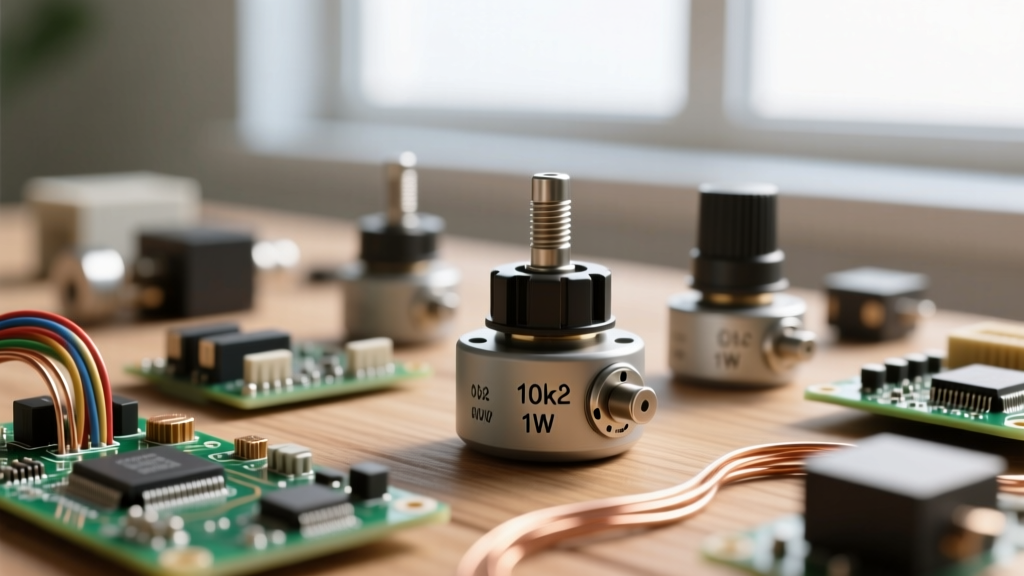
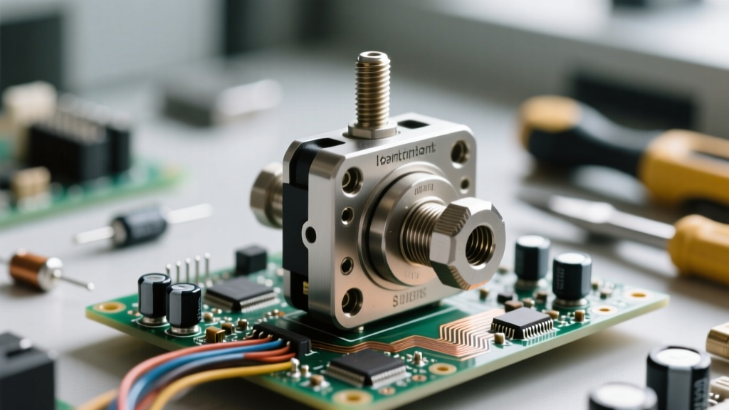
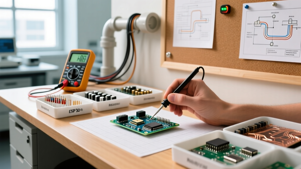
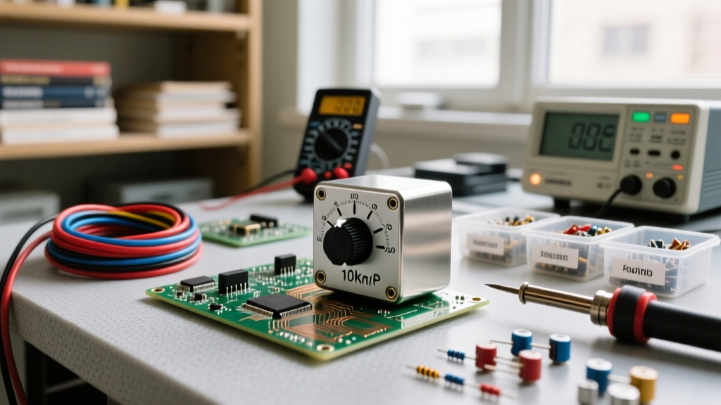
When building an electronics lab, managing a university makerspace, or stocking a production prototyping facility, the humble potentiometer is often an afterthought. Engineers and hobbyists frequently grab a generic 10k ohm pot from a bin, only to realize later that the taper is wrong for audio applications, the power rating is insufficient for a motor control circuit, or the shaft length doesn't match the enclosure. Understanding how to wire a potentiometer is only half the battle; sourcing the correct component for your specific wiring topology is what separates reliable prototypes from noisy, failing circuits.
Potentiometers (pots) are three-terminal electromechanical devices. However, how you source them—and subsequently how you wire them—dictates whether they function as a true voltage divider or a variable resistor (rheostat). Before we dive into the wiring schematics, we must address the procurement matrix. According to All About Circuits, the internal resistive element material (carbon composition, cermet, or conductive plastic) drastically affects wiper noise, rotational lifespan, and temperature stability. Sourcing a $0.15 generic carbon pot for a precision ADC feedback loop will result in jitter, whereas a $4.50 Bourns conductive plastic precision pot will yield clean, repeatable data.
How to Wire a Potentiometer: Voltage Divider vs. Rheostat
Once you have sourced the correct component, the physical wiring depends entirely on your circuit's requirements. The standard pinout for a potentiometer, when viewed from the shaft with terminals facing you, is typically Pin 1 (Counter-Clockwise / Ground), Pin 2 (Wiper), and Pin 3 (Clockwise / VCC). Let's break down the two primary ways to wire these terminals.
Topology 1: The Voltage Divider (3-Terminal Wiring)
The most common application of a potentiometer is as a voltage divider. This topology utilizes all three pins and is essential for applications like reading user input via a microcontroller's Analog-to-Digital Converter (ADC), generating reference voltages, or controlling audio volume. As detailed in the SparkFun Voltage Divider Tutorial, the output voltage is taken directly from the wiper (Pin 2).
- Pin 1: Connected to Ground (GND).
- Pin 3: Connected to Supply Voltage (VCC, e.g., 3.3V or 5V).
- Pin 2 (Wiper):strong> Connected to the ADC input or op-amp non-inverting terminal.
Pro-Tip for Audio Sourcing: If you are wiring a pot for an audio volume control, you must source a Logarithmic (Audio) taper pot (often marked with an 'A', e.g., A10K). Human hearing perceives loudness logarithmically; wiring a Linear (B10K) pot in this topology will cause the volume to jump abruptly in the first 20% of the rotation, making fine adjustments impossible.
Topology 2: The Variable Resistor / Rheostat (2-Terminal Wiring)
Sometimes you need to vary current or resistance directly, such as in a dimmer switch, a variable gain resistor for an op-amp, or a manual tuning dial for an RC oscillator. In this topology, you are wiring the potentiometer as a rheostat. You only need two connections: the wiper and one of the end terminals.
- Pin 2 (Wiper):strong> Connected to one side of your circuit.
- Pin 1 OR Pin 3: Connected to the other side of your circuit.
Critical Wiring Rule: When wiring a pot as a rheostat, you must physically tie the unused end terminal to the wiper terminal. If you leave the third pin floating and the wiper experiences a microscopic lift-off due to mechanical vibration or carbon track wear, the circuit will momentarily see infinite resistance (an open circuit). Tying the wiper to the unused terminal ensures that if wiper contact is lost, the circuit defaults to the maximum resistance of the pot rather than breaking the connection entirely. This is a common failure mode in poorly wired prototyping boards.
Inventory Matrix: Stocking the Right Potentiometers
To maintain an efficient prototyping inventory, you should not stock every value imaginable. Instead, curate a selection based on standard circuit requirements. Below is a recommended sourcing and inventory table for a modern electronics lab.
| Application / Use Case | Recommended Sourcing Specs | Example Part Number | Est. Bulk Price |
|---|---|---|---|
| Microcontroller ADC Input (Arduino/ESP32) | 10kΩ or 100kΩ, Linear (B), 0.5W, Panel Mount | Bourns PTV09A-4015F-B103 | $0.85 / unit |
| Audio Amplifier Volume Control | 10kΩ or 50kΩ, Logarithmic (A), Dual Gang | ALPS RK09K11310K | $1.45 / unit |
| PCB Trimming / Calibration (One-time set) | 1kΩ to 1MΩ, Cermet, Multi-turn (25-turn) | Bourns 3296W-1-103LF | $1.20 / unit |
| High-Current Motor Speed Control | 10Ω to 50Ω, Wirewound, 5W+ Power Rating | TT Electronics P083N | $6.50 / unit |
Microcontroller Integration: ADC Impedance and Jitter
When sourcing and wiring potentiometers for microcontrollers like the ATmega328P (used in the Arduino Uno) or the ESP32, the resistance value you source directly impacts your wiring success. Microcontroller ADCs have a sample-and-hold (S/H) capacitor inside the silicon. This capacitor needs to charge up to the voltage presented at the pin within a few microseconds.
If you source a 1MΩ potentiometer and wire it as a voltage divider, the high Thevenin equivalent resistance will prevent the internal S/H capacitor from charging fully before the ADC takes its reading. This results in severe jitter, inaccurate readings, and cross-talk between adjacent ADC pins. The ATmega328P datasheet explicitly recommends an input impedance of 10kΩ or less. Therefore, your lab inventory should heavily favor 10kΩ linear pots for general-purpose microcontroller interfacing. If you must use a high-impedance pot (e.g., 100kΩ to save battery life in a wearable device), you must wire a 0.1µF ceramic capacitor between the wiper (Pin 2) and Ground to act as an external charge reservoir.
Real-World Failure Modes from Poor Sourcing
Even if you know exactly how to wire a potentiometer, sourcing the wrong physical or electrical specification will lead to predictable hardware failures. Here are the most common issues encountered in the field:
- Thermal Destruction: Sourcing a standard 0.25W carbon pot and wiring it in series with a 12V, 1A DC motor to control speed. The pot will attempt to dissipate up to 12W of heat, resulting in immediate thermal failure, melting of the carbon track, and potentially a fire hazard. Fix: Source a high-power wirewound rheostat or, better yet, use the pot to wire a low-current signal into a MOSFET gate or PWM controller.
- Wiper Noise in Precision Circuits: Using cheap carbon composition pots in a PID controller feedback loop. As the shaft vibrates, the carbon wiper generates micro-disconnects, injecting massive voltage spikes into the op-amp. Fix: Source conductive plastic or cermet multi-turn trimpots (like the Bourns 3296 series) which offer superior wiper contact stability and resolution.
- Mechanical Binding: Sourcing a pot with a 15mm D-shaft for a panel that requires a 20mm round shaft with a bushing mount. Always verify the mechanical datasheet dimensions (shaft diameter, length, and bushing thread size) before placing bulk DigiKey or Mouser orders.
Ultimately, mastering how to wire a potentiometer is intrinsically linked to how you source them. By maintaining a strategic inventory of linear 10kΩ pots for digital logic, logarithmic pots for audio, and multi-turn cermet trimpots for calibration, you ensure that your prototyping workflow remains smooth, predictable, and free of easily avoidable hardware bugs.