
Beyond the Textbook: The Practical Science Conductor Definition
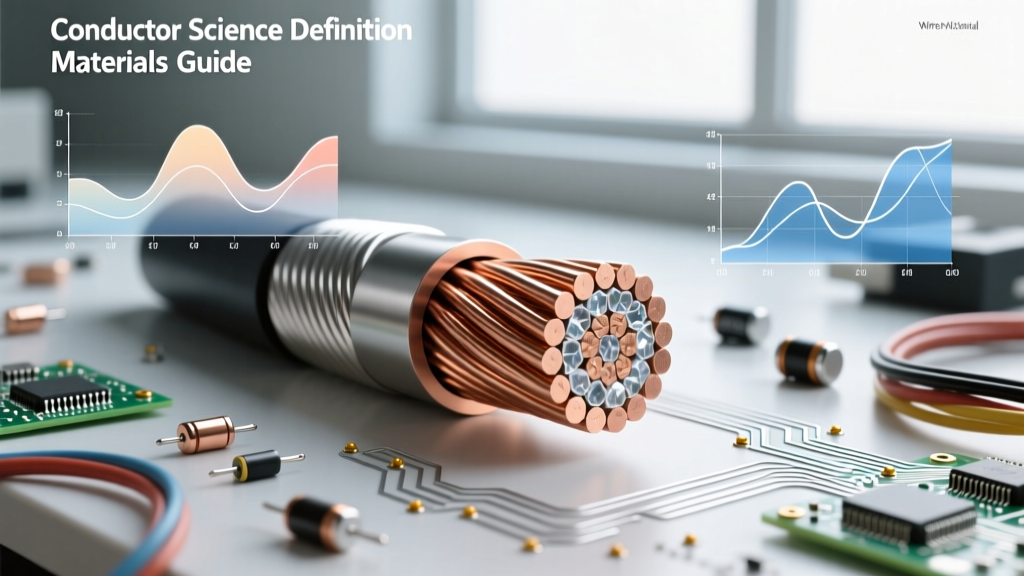
When technicians and engineers search for the strict science conductor definition, they usually encounter a basic physics textbook answer: a material that permits the free flow of electrons due to its atomic structure. While academically accurate, this definition is dangerously incomplete for professionals working in the field. In electrical safety and practical wiring design, a conductor is not just a passive pathway for current; it is a highly engineered component that must manage thermal dissipation, resist environmental degradation, and maintain structural integrity under electromagnetic stress.
From a safety perspective, the true science conductor definition encompasses the material's resistivity, its temperature coefficient of resistance, its mechanical creep rate, and its interaction with termination metals. Misunderstanding these physical properties is a leading cause of high-resistance connections, arc faults, and catastrophic electrical fires. This guide bridges the gap between atomic physics and the NFPA 70 National Electrical Code (NEC), providing a rigorous safety framework for selecting and managing conductors in real-world applications.
Atomic Structure and Thermal Runaway Risks
To understand conductor failure modes, we must look at the atomic level. In metallic conductors like copper and aluminum, the outermost electrons are loosely bound to their parent atoms, forming a "sea of electrons" that can move freely through the crystalline lattice when an electromotive force (voltage) is applied. However, this movement is not frictionless. As electrons drift, they collide with the vibrating atoms of the lattice, generating heat. This is the fundamental science behind Joule heating (I²R losses).
The safety hazard arises from the temperature coefficient of resistance. For most pure metals, as the temperature increases, the atomic lattice vibrates more violently, causing more electron collisions and increasing the electrical resistance. This creates a dangerous positive feedback loop known as thermal runaway:
- Step 1: An overloaded or poorly terminated conductor generates excess heat.
- Step 2: The heat increases the conductor's atomic lattice vibrations.
- Step 3: Electrical resistance increases, which in turn generates even more heat for the same current draw.
- Step 4: Insulation degrades, melts, or catches fire, leading to a short circuit or arc flash.
Understanding this physical reality is why the NEC mandates strict ampacity derating when multiple current-carrying conductors are bundled together in a single raceway (NEC Article 310.15). The science of heat dissipation dictates that bundled wires cannot shed thermal energy as efficiently as isolated wires, effectively lowering their safe current-carrying capacity.
Material Selection: Copper vs. Aluminum Failure Modes
The choice of conductor material drastically alters the safety profile of an electrical installation. According to data from the Copper Development Association, annealed copper is the international standard for conductivity (100% IACS), with a resistivity of approximately 1.72 × 10⁻⁸ Ω·m at 20°C. Aluminum, while significantly lighter and cheaper, has a higher resistivity of about 2.82 × 10⁻⁸ Ω·m, meaning an aluminum conductor must have a cross-sectional area roughly 1.6 times larger than copper to carry the same current safely.
The Hidden Dangers of Aluminum Creep and Oxidation
While aluminum is an excellent conductor, its mechanical and chemical properties introduce severe safety risks if not managed correctly. Aluminum is highly susceptible to cold flow (or creep). Under the constant mechanical pressure of a screw-type lug termination, aluminum slowly deforms and flows away from the pressure point over time. This reduces the contact area, increases resistance, and initiates the thermal runaway cycle described above.
Furthermore, aluminum instantly forms a tough, insulating layer of aluminum oxide when exposed to air. Unlike copper oxide, which is somewhat conductive and easily broken by mechanical friction, aluminum oxide is highly resistive and mechanically hard. If a termination is made without breaking this oxide layer and applying an anti-oxidant compound (such as Noalox), the connection will inevitably overheat.
Safety Warning: Never directly terminate aluminum conductors to copper lugs without proper bi-metallic connectors or specific plating. The galvanic potential difference between copper (cathodic) and aluminum (anodic) in the presence of ambient moisture will cause rapid galvanic corrosion, eating away the aluminum and resulting in catastrophic high-resistance failures.
Conductor Material Safety & Application Matrix
The following table synthesizes the physical properties of common conductors with their specific safety requirements and NEC applications.
| Material | Resistivity (Ω·m at 20°C) | Primary Failure Mode | Required Safety Mitigation | Typical NEC Application |
|---|---|---|---|---|
| Soft Copper | 1.72 × 10⁻⁸ | Oxidation over long periods, fatigue from vibration | Standard torque specifications, periodic thermography | Branch circuits, feeders, sensitive electronics |
| Aluminum (AA-8000) | 2.82 × 10⁻⁸ | Cold flow (creep), galvanic corrosion, oxide buildup | Anti-oxidant paste, specific torque values, CO/ALR rated devices | Service entrance cables, heavy commercial feeders |
| Silver-Plated Copper | 1.59 × 10⁻⁸ | Silver migration under high DC voltage and moisture | Hermetic sealing, strict moisture control | Aerospace, high-frequency RF, critical medical equipment |
Dielectric Boundaries: Where the Conductor Ends and Danger Begins
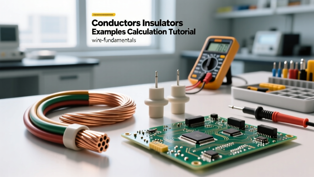
The science conductor definition is incomplete without defining its boundary: the insulation. In physics, an insulator (or dielectric) is a material where electrons are tightly bound to their atoms, preventing macroscopic current flow. However, no insulator is perfect. When the electric field strength exceeds the material's dielectric strength, the insulation undergoes avalanche breakdown, becoming a conductor and resulting in an arc fault.
In practical wiring, thermal degradation is the primary enemy of dielectric integrity. Modern building wire utilizes advanced polymers, but their safety limits are strictly defined by IEEE and UL testing standards:
- THHN (Thermoplastic High Heat-resistant Nylon-coated): Rated for 90°C in dry locations. The nylon jacket provides excellent mechanical and chemical resistance, but thermoplastic insulation will soften and melt if exposed to temperatures exceeding its rating, potentially exposing the live conductor.
- XHHW-2 (Cross-linked Polyethylene): Rated for 90°C in both wet and dry locations. The cross-linking process creates a thermoset polymer that will not melt under high heat; instead, it chars and maintains its physical shape, offering superior short-circuit survivability and safety.
When sizing conductors, safety professionals must remember NEC Article 110.14(C). Even if you use 90°C rated XHHW-2 wire, the ampacity must generally be based on the 75°C or 60°C column of NEC Table 310.16, because the termination lugs on most standard breakers and panels are only tested and rated for those lower temperatures. Ignoring this boundary is a frequent cause of panel fires.
Advanced Diagnostic Protocols for Conductor Health
Relying solely on visual inspections is insufficient for verifying conductor safety. Because the science of high-resistance connections dictates that failures occur at the molecular level before becoming visible, electrical maintenance teams must employ advanced diagnostic protocols.
1. Micro-Ohmmeter Testing
Standard digital multimeters (DMMs) lack the resolution to detect micro-ohm changes in busbar joints or heavy feeder terminations. A dedicated micro-ohmmeter injects a high DC current (often 10A to 100A) through the joint and measures the millivolt drop. By comparing the measured resistance against baseline manufacturer data, technicians can identify creeping connections long before they reach thermal failure thresholds.
2. Infrared (IR) Thermography
Thermal imaging cameras detect the infrared radiation emitted by conductors. Because heat generation follows the I²R formula, a loose connection carrying a heavy load will appear as a distinct hot spot on an IR camera. Safety protocols dictate that a temperature differential (ΔT) of just 15°C above ambient or adjacent phases warrants immediate investigation, while a ΔT of 40°C indicates an imminent, critical failure requiring an emergency shutdown.
Conclusion: Respecting the Physics of Electrical Safety
The true science conductor definition extends far beyond the simple flow of electrons. It is a complex interplay of metallurgy, thermodynamics, and chemistry. By respecting the physical limitations of conductor materials, understanding the thermal runaway mechanics of high-resistance connections, and strictly adhering to the dielectric boundaries set by insulation ratings, electrical professionals can design and maintain systems that are fundamentally safe. Always anchor your field practices in the hard science of material properties and the rigorous safety codes derived from them.