
The Physics of Unidirectional Flow: What is Direct Current?
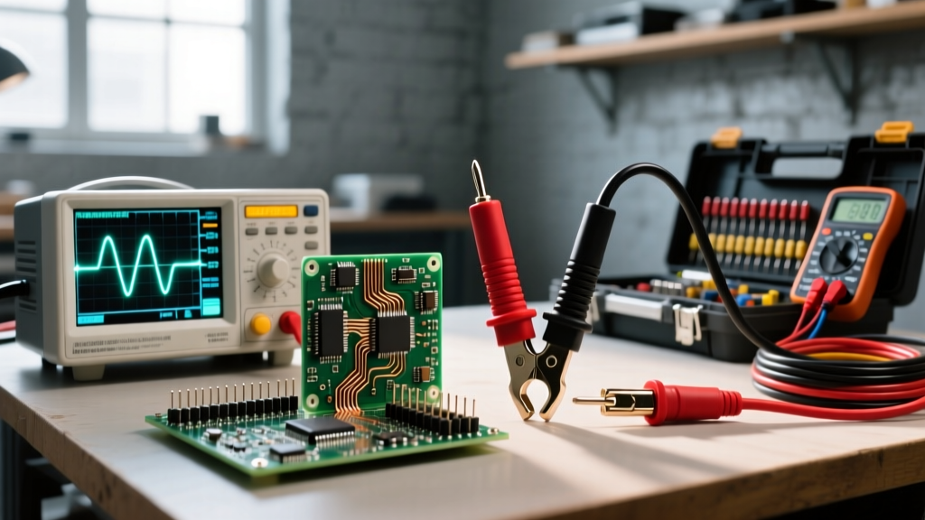
Direct current (DC) represents the continuous, unidirectional flow of electrical charge. Unlike alternating current (AC), which periodically reverses direction in a sinusoidal waveform, DC maintains a constant polarity. Electrons move steadily from the negative terminal (anode) to the positive terminal (cathode) through a conductive medium. This fundamental behavior is the backbone of modern electronics, battery storage systems, automotive electrical networks, and solar photovoltaic (PV) arrays.
According to the foundational electrical theory outlined by All About Circuits, the steady-state nature of DC means that the voltage level remains theoretically constant over time, assuming an ideal power source. In practical applications, however, DC sources like batteries experience a gradual voltage sag as their chemical energy is depleted, while rectified DC from AC sources may contain residual 'ripple' that requires capacitive filtering. Understanding these nuances is critical for electrical engineers and DIYers alike, particularly when sizing conductors to handle continuous thermal loads.
DC vs. AC: Why Electron Behavior Dictates Wire Selection
When sizing wires, the type of current flowing through the conductor fundamentally alters how the wire behaves thermally and electrically. While DC and AC share the same basic resistance formulas, the physical movement of electrons introduces distinct engineering challenges.
The Absence of the Skin Effect
In AC circuits operating at standard frequencies (50Hz or 60Hz), the alternating magnetic fields push electrons toward the outer periphery of the conductor—a phenomenon known as the 'skin effect.' Because the center of the wire carries less current, the effective cross-sectional area is reduced, increasing the wire's effective AC resistance. Direct current, however, flows uniformly across the entire cross-section of the wire. Consequently, a specific AWG (American Wire Gauge) copper conductor will have a slightly lower DC resistance than its AC resistance. While this sounds advantageous, the real challenge of DC wiring lies not in high-frequency skin effects, but in system voltage.
The Low-Voltage, High-Current Trap
The most critical factor in DC wire sizing is the relationship between voltage, current, and power, defined by Watt's Law (Power = Voltage × Current). Most DC systems—such as automotive, marine, and off-grid battery banks—operate at low voltages (12V, 24V, or 48V). To deliver the same amount of power as a standard 120V AC household circuit, a low-voltage DC system must draw exponentially higher current.
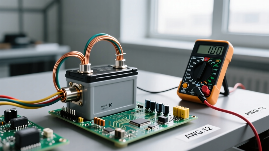
Consider a 1,200-watt load. On a 120V AC circuit, this draws a manageable 10 amps, which can easily be supported by standard 14 AWG copper wire. However, on a 12V DC battery bank, that same 1,200-watt load demands 100 amps. This massive surge in current requires a heavy-duty 2 AWG or 1 AWG conductor to prevent thermal melting and excessive voltage drop. This high-current reality makes DC wire sizing far more demanding than standard residential AC wiring.
Calculating DC Voltage Drop: A Practical Framework
Voltage drop is the silent killer of low-voltage DC systems. Because the baseline voltage is already low, even a small loss of electrical pressure across a wire run can prevent equipment from operating. For instance, a 1.5-volt drop on a 120V AC line is negligible (1.25%), but a 1.5-volt drop on a 12V DC system represents a massive 12.5% loss, which will cause LED lights to dim, motors to overheat, and inverters to trigger low-voltage alarms.
The standard formula for calculating DC voltage drop in a single-phase, two-wire circuit is:
Voltage Drop (VD) = (2 × K × I × L) / CM
- K = Specific resistance of the conductor (12.9 ohms per mil-foot for copper at 75°C)
- I = Current in Amperes
- L = One-way length of the wire in feet
- CM = Circular Mils of the wire cross-section
To illustrate how system voltage dictates wire sizing, examine the table below. This data models a 1,200W continuous load running over a 20-foot wire run (40 feet total round-trip) using 4 AWG copper wire (41,740 CM).
| System Voltage | Current Draw (Amps) | Voltage Drop (Volts) | Percentage Drop | Acceptable? |
|---|---|---|---|---|
| 12V DC | 100A | 1.23V | 10.25% | No (Exceeds 3%) |
| 24V DC | 50A | 0.61V | 2.54% | Yes (Under 3%) |
| 48V DC | 25A | 0.31V | 0.64% | Yes (Optimal) |
Note: The National Electrical Code (NEC) generally recommends keeping voltage drop under 3% for branch circuits and 5% for the entire feeder and branch combined to ensure system efficiency.
Industry Standards and Material Selection for DC Wiring
Sizing a DC wire isn't just about picking the right AWG; it is equally about selecting the correct insulation and conductor material for the environment. The NFPA 70 (National Electrical Code) and specialized marine boards have strict guidelines for DC installations.
Marine and Automotive Applications (ABYC Standards)
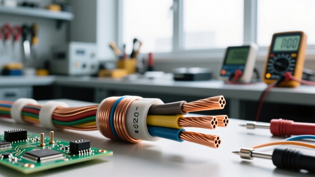
In marine and automotive environments, DC wiring is subjected to vibration, moisture, and corrosive salt air. The American Boat and Yacht Council (ABYC) E-11 standard strictly mandates the use of stranded, tinned copper wire for DC systems. Bare copper wire exposed to humid, salty environments will rapidly oxidize, turning the conductor green and brittle. This oxidation increases resistance at the termination points, leading to localized heating and potential fires. Tinning the copper strands coats them in a microscopic layer of tin, preventing galvanic corrosion and ensuring long-term conductivity. Furthermore, marine DC wire must use fine-stranding (Type III) to withstand the constant mechanical vibration of engines and hull impacts without suffering from metal fatigue and wire breakage.
Solar PV Arrays (NEC Article 690)
Solar photovoltaic systems present a unique DC challenge: they combine extremely high DC voltages (often 600V to 1000V DC) with outdoor exposure. Standard THHN wire pulled through conduit is insufficient for exposed solar runs. NEC Article 690 requires the use of specialized PV Wire or USE-2 cable. PV Wire features a much thicker insulation jacket, dual-layer protection, and is heavily rated for UV resistance and extreme temperature fluctuations. Using standard AC building wire for outdoor DC solar runs will result in insulation cracking, UV degradation, and catastrophic arc faults within a few years.
Practical Troubleshooting: Identifying DC Wiring Failures
Because DC systems often operate at high currents, the termination points (lugs, busbars, and breakers) are the most common failure points. A loose or improperly crimped DC lug will introduce micro-ohms of resistance. While negligible in low-current signal wiring, in a 150A DC inverter circuit, that micro-resistance will generate massive heat according to Joule's Law (Heat = I²R).
To troubleshoot and verify DC wiring integrity, professional electricians rely on the Millivolt Drop Test. Instead of using an infrared thermometer—which only measures surface temperature and is affected by ambient air—a technician uses a digital multimeter to measure the voltage drop directly across the connection joint while the system is under full load.
Expert Rule of Thumb: A healthy, properly crimped DC lug carrying 100 Amps should exhibit a voltage drop of less than 1.0 millivolt (0.001V) across the joint. If your multimeter reads 5mV or higher, the connection is failing, generating excess heat, and requires immediate re-termination.
Mastering direct current fundamentals requires moving beyond the simple concept of 'one-way flow.' By respecting the high-current demands of low-voltage systems, calculating voltage drop rigorously, and selecting environment-specific materials like tinned copper or PV-rated insulation, you ensure that your DC electrical infrastructure remains safe, efficient, and reliable for decades.