
Decoding the 40-Pin Header: Physical vs. Logical Mapping
When integrating sensors, actuators, or secondary microcontrollers into a Raspberry Pi ecosystem, understanding the raspi gpio pinout is the critical first step. Unlike standard Arduino boards where digital pins are sequentially numbered and universally tolerant, the Raspberry Pi utilizes a 40-pin header that mixes power rails, grounds, and multifunctional logic pins. The physical layout has remained largely consistent since the Raspberry Pi 1 Model B+, but the underlying configuration and architectural handling of these pins have evolved significantly, especially with the introduction of the Raspberry Pi 5.
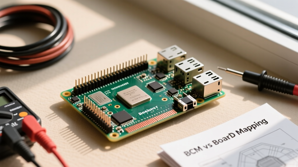
The 40-pin header contains exactly 26 usable GPIO (General Purpose Input/Output) pins, alongside dedicated power pins (3.3V and 5V) and multiple ground (GND) connections. A common beginner mistake is assuming that the physical pin number correlates to the software GPIO number. For instance, Physical Pin 11 is actually GPIO 17 in the Broadcom naming scheme. Misinterpreting this mapping is the leading cause of configuration errors and silent hardware failures in DIY electronics projects.
BCM vs. BOARD: Choosing Your Numbering Scheme
Before writing a single line of configuration code, you must decide on a numbering scheme. The Python RPi.GPIO library and the C-based libgpiod tools require you to declare your mapping paradigm upfront.
- BOARD Numbering: This refers to the physical pin numbers on the header (1 through 40). It is hardware-agnostic and remains identical across almost all Raspberry Pi models. If you are looking straight down at the board with the USB ports facing you, Pin 1 is the top-left 3.3V pin, and Pin 2 is the top-right 5V pin.
- BCM (Broadcom SOC Channel) Numbering: This maps to the internal GPIO numbers of the Broadcom system-on-chip (or the RP1 chip on the Pi 5). For example, physical Pin 3 is BCM 2. This is the preferred method for advanced makers, as it aligns directly with the hardware device tree and alternate bus functions.
Configuration Snippet: Setting the Mode in Python
import RPi.GPIO as GPIO

# Set the numbering scheme to Broadcom
GPIO.setmode(GPIO.BCM)

# Configure BCM Pin 18 (Physical Pin 12) as an output
GPIO.setup(18, GPIO.OUT, initial=GPIO.LOW)

# Configure BCM Pin 24 (Physical Pin 18) as an input with internal pull-up
GPIO.setup(24, GPIO.IN, pull_up_down=GPIO.PUD_UP)
Always initialize your GPIO states explicitly. Failing to set an initial state can cause a momentary voltage spike or floating state during the script's boot sequence, which can trigger unintended relay switching or motor jitter.
Critical Voltage Thresholds and Hardware Protection
The most destructive assumption makers carry over from the Arduino world is 5V tolerance. The Raspberry Pi GPIO operates strictly at 3.3V logic. The absolute maximum voltage rating on any GPIO pin is 3.6V. Feeding a 5V signal from an Arduino UNO, a standard ultrasonic sensor (like the HC-SR04), or a 5V I2C display directly into a Pi GPIO pin will forward-bias the internal ESD protection diodes. This typically shorts the 3.3V rail, overheating the PMIC (Power Management IC) and permanently bricking the SoC.
The 5V Tolerance Myth and Level Shifting
To safely interface 5V components with the raspi gpio pinout, you must use a logic level shifter. However, not all shifters are created equal:
- Push-Pull Shifters (e.g., 74AHCT125): Ideal for one-way communication like driving 5V WS2812B addressable LEDs or standard SPI displays.
- Bi-Directional MOSFET Shifters (e.g., BSS138): Mandatory for open-drain protocols like I2C. The BSS138 circuit safely translates the 3.3V SDA/SCL lines to 5V without fighting the pull-up resistors on the bus.
- Voltage Dividers: A simple resistor divider (e.g., 1kΩ and 2kΩ) is sufficient for reading a 5V digital HIGH/LOW signal, such as the echo pin of an HC-SR04 sensor, but it is too slow for high-speed bus communication.
For a deep dive into bidirectional translation, the Adafruit Level Shifting Basics guide provides excellent schematics for MOSFET-based I2C protection.
Dedicated Communication Buses: I2C, SPI, and UART
The true power of the raspi gpio pinout lies in its hardware-accelerated communication buses. While you can bit-bang protocols on any pin, utilizing the dedicated hardware pins offloads the timing constraints from the Linux CPU, eliminating OS-level jitter.
I2C Configuration and Pull-Up Dynamics
Hardware I2C1 is mapped to BCM 2 (SDA, Pin 3) and BCM 3 (SCL, Pin 5). Crucially, the Raspberry Pi motherboard includes onboard 1.8kΩ pull-up resistors tied to the 3.3V rail for these specific pins. If you are connecting a 5V I2C device, you must disable the device's onboard 5V pull-ups and rely on a BSS138 level shifter to bridge the 3.3V Pi pull-ups to the 5V device.
SPI0 and Chip Select (CE) Lines
The primary SPI0 bus utilizes BCM 10 (MOSI), BCM 9 (MISO), and BCM 11 (SCLK). The Chip Enable lines are BCM 8 (CE0, Pin 24) and BCM 7 (CE1, Pin 26). When configuring SPI displays like the ILI9341, ensure your Python library (such as spidev) is configured to use the correct CE line, or manually toggle a standard GPIO pin as a software chip-select if you are daisy-chaining multiple SPI peripherals.
UART and the Serial Console Conflict
BCM 14 (TXD, Pin 8) and BCM 15 (RXD, Pin 10) handle hardware UART. By default, Raspberry Pi OS maps the Linux serial console to these pins for headless debugging. To use them for communicating with an Arduino or a GPS module, you must run sudo raspi-config, navigate to Interface Options > Serial Port, disable the login shell over serial, but enable the serial port hardware.
Raspberry Pi 5 and the RP1 Southbridge Shift
If you are configuring a Raspberry Pi 5, the physical raspi gpio pinout remains identical for backward compatibility, but the internal architecture has fundamentally changed. The Pi 5 offloads all GPIO, I2C, SPI, and UART handling to a custom RP1 southbridge chip.
This architectural shift means that older C/C++ libraries that directly accessed the Broadcom memory registers via /dev/mem (such as the legacy bcm2835 library or outdated versions of WiringPi) will fail or cause kernel panics on the Pi 5. Configuration on the Pi 5 strictly requires the use of the standard Linux libgpiod character device interface or updated Python wrappers that communicate with the RP1 daemon. Always verify your library's Pi 5 compatibility before deploying production code.
Quick-Reference GPIO Function Table
Below is a configuration cheat sheet for the most commonly used alternate functions on the 40-pin header. For a complete, interactive map, makers should bookmark the definitive Pinout.xyz Raspberry Pi GPIO database.
| Physical Pin | BCM GPIO | Primary Function | Hardware Bus / Alt Function |
|---|---|---|---|
| 3 | 2 | GPIO 2 | I2C1 SDA (Includes 1.8k Pull-up) |
| 5 | 3 | GPIO 3 | I2C1 SCL (Includes 1.8k Pull-up) |
| 8 | 14 | GPIO 14 | UART0 TXD |
| 10 | 15 | GPIO 15 | UART0 RXD |
| 12 | 18 | GPIO 18 | PCM_CLK / Hardware PWM0 |
| 19 | 10 | GPIO 10 | SPI0 MOSI |
| 21 | 9 | GPIO 9 | SPI0 MISO |
| 23 | 11 | GPIO 11 | SPI0 SCLK |
| 32 | 12 | GPIO 12 | PWM0 / Hardware PWM1 |
| 33 | 13 | GPIO 13 | PWM1 / Hardware PWM1 |
Troubleshooting Common Pinout Configuration Errors
Even with a perfect wiring diagram, software configuration mismatches can lead to frustrating debugging sessions. Here are the most frequent failure modes encountered when configuring the raspi gpio pinout:
- Floating Inputs Triggering Interrupts: If you configure a pin as
GPIO.INwithout specifying a pull-up or pull-down resistor, the pin acts as an antenna. Electromagnetic interference from nearby AC lines or switching power supplies will cause phantom interrupts. Always usepull_up_down=GPIO.PUD_UPorPUD_DOWNin your setup function. - PWM Audio Interference: The Raspberry Pi generates analog audio via PWM on specific GPIO pins (historically BCM 40 and 41, routed to the 3.5mm jack). If your custom PWM configuration on nearby pins experiences severe jitter, ensure you are using the dedicated hardware PWM pins (BCM 12, 13, 18, 19) rather than relying on software-based PWM, which is heavily impacted by Linux background tasks.
- I2C Bus Lockups: If an I2C device crashes and holds the SDA line LOW, the Pi will refuse to communicate on the bus upon reboot. To clear this, you can temporarily configure the SCL pin (BCM 3) as a standard GPIO output, manually toggle it HIGH/LOW nine times to force the slave device to release the bus, and then reinitialize the I2C kernel module.
For official documentation on device tree overlays and advanced pin multiplexing, refer to the Raspberry Pi GPIO and Configuration Documentation. Mastering the physical and logical boundaries of the Pi's header ensures your embedded projects remain robust, safe, and highly performant.