
The Raspberry Pi 5 represents a generational leap in single-board computing, but for hardware hackers and embedded engineers, the most critical changes lie beneath the surface of the familiar 40-pin header. While the physical Raspberry Pi 5 GPIO pinout maintains mechanical backward compatibility with previous models, the underlying silicon architecture and electrical behaviors have undergone a massive overhaul. Understanding these changes is no longer optional; it is a strict requirement for preventing hardware damage and ensuring software compatibility in your embedded projects.
The Silicon Paradigm Shift: Enter the RP1 Southbridge
To truly understand the Pi 5 pinout, you must first understand how the signals are routed. In the Raspberry Pi 1 through 4, the Broadcom System-on-Chip (SoC) handled both the primary compute tasks and the GPIO peripheral management. The Raspberry Pi 5 abandons this monolithic approach.
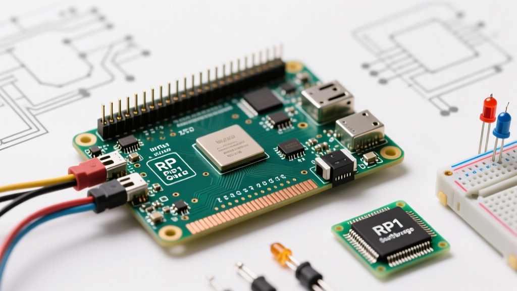
The compute duties are handled by the quad-core Arm Cortex-A76 based BCM2712 processor. However, all I/O operations—including the 40-pin GPIO header, USB controllers, and Ethernet—are offloaded to a custom-designed southbridge chip called the RP1. The RP1 communicates with the main BCM2712 SoC via an internal PCIe Gen 2.0 link.
Why does this matter for your wiring and code? Because the GPIO pins are no longer memory-mapped directly to the main CPU's peripheral bus. This architectural shift fundamentally alters latency profiles, DMA (Direct Memory Access) capabilities, and how operating systems interact with the pins. It also means that legacy libraries relying on direct memory register manipulation will fail or cause kernel panics on the Pi 5.
Decoding the 40-Pin Header Map
The physical layout of the Raspberry Pi 5 GPIO pinout remains a 2x20 male header. Below is a functional breakdown of the most critical pins used in DIY electronics, sensor integration, and bus communication.
| Pin | Function (BCM / Alt) | Pin | Function (BCM / Alt) |
|---|---|---|---|
| 1 | 3V3 Power (Max 50mA draw) | 2 | 5V Power (Direct from PSU) |
| 3 | GPIO 2 (SDA1 / I2C) | 4 | 5V Power |
| 5 | GPIO 3 (SCL1 / I2C) | 6 | Ground (GND) |
| 7 | GPIO 4 (GPCLK0) | 8 | GPIO 14 (TXD / UART) |
| 9 | Ground (GND) | 10 | GPIO 15 (RXD / UART) |
| 11 | GPIO 17 (SPI1 CE1) | 12 | GPIO 18 (PCM CLK / PWM0) |
| 13 | GPIO 27 (PWM1) | 14 | Ground (GND) |
| 15 | GPIO 22 | 16 | GPIO 23 |
| 17 | 3V3 Power | 18 | GPIO 24 |
| 19 | GPIO 10 (MOSI / SPI0) | 20 | Ground (GND) |
| 21 | GPIO 9 (MISO / SPI0) | 22 | GPIO 25 |
| 23 | GPIO 11 (SCLK / SPI0) | 24 | GPIO 8 (CE0 / SPI0) |
| 25 | Ground (GND) | 26 | GPIO 7 (CE1 / SPI0) |
Power and Ground Distribution
The 5V pins (Pins 2 and 4) are tied directly to the USB-C power input. On the Pi 5, which supports 5V/5A (25W) PD negotiation, these pins can theoretically supply substantial current, but you must account for the board's own consumption. The 3.3V rail (Pins 1 and 17) is generated by an onboard switching regulator. Drawing more than 50mA from the 3.3V pins is highly discouraged, as it can cause voltage sag and destabilize the RP1 chip's logic levels.
Dedicated Communication Interfaces
- I2C (Pins 3 & 5): GPIO 2 (SDA) and GPIO 3 (SCL). The RP1 chip features internal pull-up resistors, but their values are relatively high (often >50kΩ). For high-speed I2C or long wire runs, external 4.7kΩ pull-ups to the 3.3V rail are mandatory.
- SPI0 (Pins 19, 21, 23, 24, 26): The primary high-speed serial bus. Capable of much higher clock speeds on the Pi 5 due to the RP1's upgraded DMA engines, making it ideal for driving TFT displays or high-resolution ADCs.
- UART (Pins 8 & 10): GPIO 14 (TX) and GPIO 15 (RX). Crucial for headless debugging or communicating with GPS modules and microcontrollers like the Arduino Nano.
Pi 5 vs. Pi 4: Critical Hardware Divergences
While the 40-pin header is physically identical, several functional changes impact project migration. According to the official Raspberry Pi documentation, the most notable omission is the removal of the analog audio output. On the Pi 4, PWM pins could be remapped to drive a basic analog audio jack; on the Pi 5, this legacy audio circuitry has been completely stripped from the board to save space and reduce noise.
Furthermore, the Pi 5 introduces dedicated JST SH connectors adjacent to the GPIO header. These include a 4-pin PWM fan connector (which eliminates the need to wire 5V fans directly to the GPIO header and allows for precise RPM telemetry) and a 3-pin RTC (Real Time Clock) connector for a CR2032 battery backup. If you are designing custom HATs (Hardware Attached on Top), you must account for these new physical footprints to avoid mechanical clearance issues.
Software Stack Upheaval: Navigating the libgpiod Transition
The most painful realization for veteran makers booting up a Pi 5 is that the legendary pigpio and RPi.GPIO Python libraries are effectively dead. Because these libraries relied on direct memory mapping to the Broadcom SoC's peripheral registers, they cannot see the RP1 southbridge over the PCIe bus.
To manipulate the Raspberry Pi 5 GPIO pinout in software, the ecosystem has standardized around the Linux kernel's character device interface via libgpiod. For Python developers and C++ engineers who need the low-latency, high-frequency toggling that pigpio once provided, the community has rallied around the lg library by joan2937. The lg library communicates with the RP1 chip using the proper kernel drivers and user-space SPI/I2C daemons, restoring the ability to generate precise software PWM and servo control signals without requiring root-level memory hacks.
Real-World Wiring Safety and Logic Level Translation
Embedded engineers must treat the Pi 5's I/O with extreme caution. The RP1 southbridge operates strictly at 3.3V logic.
CRITICAL WARNING: The Raspberry Pi 5 GPIO pins are NOT 5V tolerant. Applying 5V to any data pin (such as those connected to 5V Arduino sensors, HC-SR04 ultrasonic modules, or WS2812B LED strips) will instantly and permanently destroy the RP1 chip's I/O pads, and potentially short the entire PCIe bus.
Implementing Safe Translation Circuits
When interfacing the Pi 5 with 5V logic families (like standard 74HC series ICs or older AVR microcontrollers), you must use a logic level shifter.
- For Bidirectional Buses (I2C): Use a MOSFET-based translator like the BSS138 breakout board. It safely translates 3.3V SDA/SCL signals to 5V without frying the RP1, while respecting the open-drain nature of the I2C protocol.
- For Unidirectional Signals (Ultrasonic Sensors): A simple resistor voltage divider (e.g., 1kΩ in series, 2kΩ to ground) on the Pi's RX line is sufficient to drop a 5V echo pulse down to a safe ~3.3V.
- For High-Speed Multi-Bit Data (LED Strips): Utilize an 8-channel bi-directional translator IC like the TXS0108E or SN74LV8T245 to safely drive 5V WS2812B addressable LEDs from the Pi 5's 3.3V SPI or GPIO outputs.
Mastering the Raspberry Pi 5 GPIO pinout requires unlearning some assumptions from the Pi 4 era. By respecting the RP1 southbridge architecture, adopting modern libgpiod software paradigms, and strictly enforcing 3.3V logic boundaries, you can harness the massive I/O bandwidth of the Pi 5 for next-generation robotics, automation, and data-logging projects.