
Introduction: Learning the Raspberry Pi 3B+ Pinout Through Real Builds
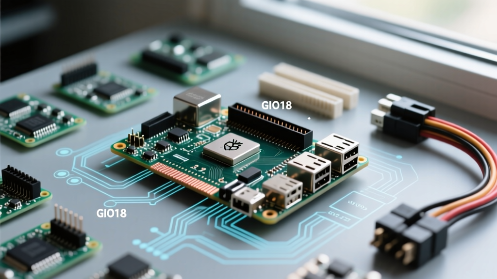
The Raspberry Pi 3B+ remains a legendary workhorse in the maker community. Despite the release of newer iterations, its balance of processing power, integrated Wi-Fi, and affordable secondary-market pricing makes it a staple for Home Assistant nodes, retro gaming cabinets, and environmental monitors. However, transitioning from software to hardware requires a deep understanding of the raspberry pi 3b+ pinout. Rather than memorizing a dry datasheet, the most effective way to master the 40-pin GPIO header is by examining how the community actually wires real-world projects.
In this showcase, we break down the anatomy of the 3B+ header, highlight specific wiring quirks unique to this board revision, and explore three community-driven projects that leverage I2C, UART, and Hardware PWM. Whether you are building a smart home sensor or a LoRa gateway, these practical insights will save you from fried components and boot failures.
The 40-Pin Header: Power Rails and the 3B+ Voltage Quirk
Before connecting any logic pins, we must address the power rails. The 40-pin header provides 3.3V (Pins 1, 17), 5V (Pins 2, 4), and multiple Ground pins. A critical piece of E-E-A-T knowledge specific to the Raspberry Pi 3B+ involves its power management architecture.
The 3B+ utilizes the MXL7704 Power Management IC (PMIC). Unlike older models, the 5V pins on the GPIO header are directly tied to the 5V input from the micro-USB port. If you are powering the Pi via the micro-USB connector and attempt to draw significant current from the 5V GPIO pins to drive relays or servo motors, you will experience severe voltage sag. The community consensus for heavy-load projects is to bypass the micro-USB entirely and 'backfeed' 5V directly through the GPIO 5V pins (Pin 2 or 4) using a high-quality 5V 3A buck converter. Note: Backfeeding bypasses the onboard polyfuse, so ensure your external power supply has its own over-current protection.
Community Showcase 1: I2C BME280 Smart Home Climate Node
One of the most popular community projects for the 3B+ is a multi-room climate node feeding data into Home Assistant via MQTT. The BME280 sensor is the gold standard here, measuring temperature, humidity, and barometric pressure. It communicates via I2C, which maps beautifully to the top-left pins of the header.
Wiring the I2C Bus
- Pin 1 (3.3V): VCC on the BME280. Never connect a 3.3V sensor to Pin 2 (5V), or you will instantly destroy the sensor's internal logic.
- Pin 3 (GPIO 2 / SDA1): I2C Data line.
- Pin 5 (GPIO 3 / SCL1): I2C Clock line.
- Pin 6 (GND): Ground reference.
According to the Adafruit BME280 wiring guide, the Raspberry Pi's internal I2C pull-up resistors are typically sufficient for short wire runs (under 30cm). However, community members building whole-house nodes often run Cat5e cable up to 3 meters to reach attic spaces. At this length, the Pi's internal 1.8kΩ pull-ups are too weak, resulting in corrupted I2C packets. The fix? Solder external 4.7kΩ pull-up resistors between the SDA/SCL lines and the 3.3V rail at the sensor end of the cable.
Community Showcase 2: The UART Serial Console & LoRa Gateway
UART (Universal Asynchronous Receiver-Transmitter) is essential for debugging headless Pi setups or communicating with GPS and LoRa radio modules. On the pinout, UART TX is Pin 8 (GPIO 14) and RX is Pin 10 (GPIO 15). But the 3B+ harbors a notorious quirk that trips up beginners: the Bluetooth Serial Conflict.
Solving the Mini-UART vs. PL011 Swap
On the Pi 3B and 3B+, the primary hardware UART (PL011) is routed to the onboard Bluetooth module, leaving the GPIO header with the secondary 'mini-UART'. The mini-UART lacks a stable baud rate because it is tied to the core clock frequency, which fluctuates under load. If you wire a LoRa module (like the RFM95W) to Pins 8 and 10 out of the box, your serial data will be garbled.
The community workaround is to force the Bluetooth module onto the mini-UART, freeing up the stable PL011 UART for the GPIO header. You achieve this by editing the /boot/config.txt file:
enable_uart=1
dtoverlay=miniuart-bt
This single configuration change is the difference between a failing DIY LoRa gateway and a rock-solid mesh network node. For a complete visual map of these alternate functions, makers constantly rely on the interactive diagrams at Pinout.xyz, which remains the definitive visual reference for Broadcom BCM2837B0 pin mappings.
Community Showcase 3: Hardware PWM for Server Fan Control
Many makers use the Pi 3B+ as a lightweight Proxmox or Docker server. Because the 3B+ is notorious for thermal throttling (its CPU hits 60°C+ under sustained load), the community frequently mods standard 5V PC fans to run quietly using Pulse Width Modulation (PWM).
While software PWM can be run on any pin, it causes CPU jitter and audio interference. The 3B+ pinout features a dedicated Hardware PWM pin:
- Pin 12 (GPIO 18 / PWM0): This pin is driven by a dedicated hardware clock, ensuring a perfectly stable square wave regardless of CPU load.
By wiring Pin 12 to the base of a 2N2222 NPN transistor (with a 1kΩ current-limiting resistor), makers can switch a 12V PC fan on and off thousands of times per second. Using Python's gpiozero library, the community writes scripts that read the Pi's internal thermal sensor and dynamically adjust the PWM duty cycle, keeping the 3B+ ice-cold and completely silent during idle Home Assistant operations.
The Boot-Hazard Pin Matrix
Not all GPIO pins are created equal. The Broadcom SoC samples specific pins during the boot sequence to determine the boot source (USB, SD Card, or EEPROM). If you wire a sensor or relay that pulls these pins LOW or HIGH at the wrong time, your Pi 3B+ will fail to boot. Always consult this matrix before designing a custom HAT or wiring a permanent enclosure.
| Physical Pin | GPIO (BCM) | Boot Behavior & Hazard | Safe for Inputs? |
|---|---|---|---|
| 27 | GPIO 0 | Must be HIGH to boot. Pulled LOW by default. | No (Causes boot hang) |
| 28 | GPIO 1 | Must be HIGH to boot. Pulled LOW by default. | No (Causes boot hang) |
| 3 | GPIO 2 | I2C SDA. Has onboard 1.8kΩ pull-up to 3.3V. | Yes (Open-drain only) |
| 5 | GPIO 3 | I2C SCL. Has onboard 1.8kΩ pull-up to 3.3V. | Yes (Open-drain only) |
| 7 | GPIO 4 | Default 1-Wire interface. Safe, but pulled HIGH. | Yes |
Community Tip: If you must use GPIO 0 or 1 for a specific hardware interrupt, ensure your circuit includes a pull-up resistor to 3.3V so the pin reads HIGH during the critical first 2 seconds of power-on.
Longevity and Thermal Best Practices
Mastering the raspberry pi 3b+ pinout is only half the battle; preserving the hardware is the other. The 3B+ introduced a metal RF shield and a thicker PCB for better heat dissipation, but it still requires active cooling for GPIO-heavy projects. When wiring components like the BME280 or UART modules, keep your I2C and Serial traces away from the CPU and the MXL7704 PMIC, as these generate localized heat that can drift analog sensor readings.
Furthermore, the official Raspberry Pi GPIO documentation strictly advises limiting the current draw to 16mA per pin, with a total board limit of 50mA across all GPIO pins combined. If your community project requires driving multiple LEDs, optocouplers, or relays, use a ULN2803 Darlington transistor array or a dedicated I2C GPIO expander (like the MCP23017) powered directly from the 5V rail.
Conclusion
The Raspberry Pi 3B+ pinout is a gateway to endless DIY possibilities, provided you respect the hardware's electrical boundaries. By understanding the 3B+ specific quirks—like the UART Bluetooth swap, the 5V backfeed requirements, and the boot-hazard pins—you can design projects that are not just functional on a workbench, but reliable enough to run 24/7 in a smart home or remote environmental station. Grab your multimeter, verify your I2C addresses, and start building.