
The Legacy of the 40-Pin Header: Raspberry Pi 3 Pinout Basics
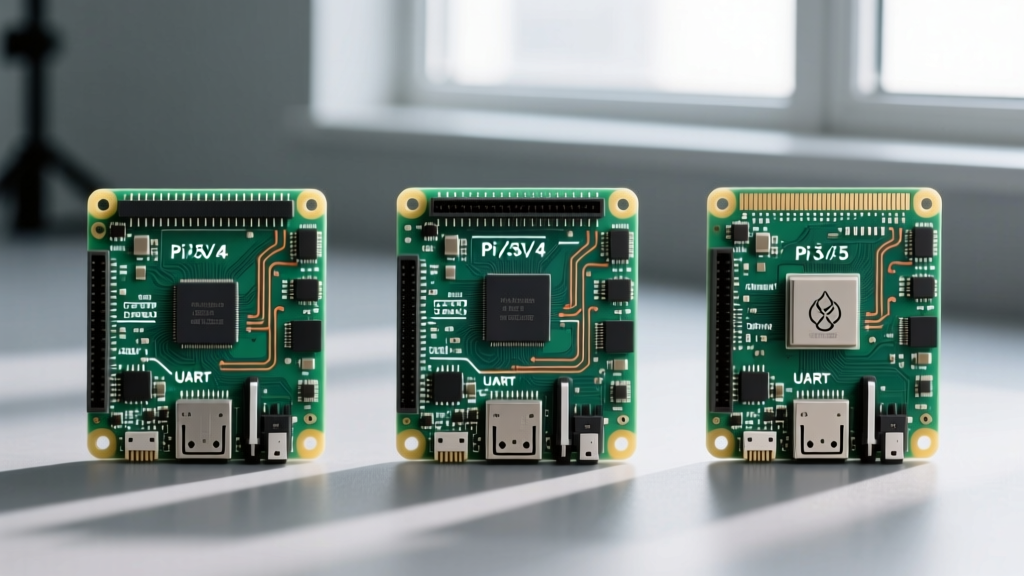
The 40-pin GPIO header is the undisputed backbone of the Raspberry Pi ecosystem. While the physical footprint of the header has remained identical since the Raspberry Pi 1 Model B+, the underlying hardware architecture driving those pins has evolved drastically. For hardware engineers, makers, and industrial integrators, understanding the nuances of the Raspberry Pi 3 pinout compared to newer iterations like the Pi 4 and Pi 5 is critical for ensuring project reliability, signal integrity, and power safety.
The Raspberry Pi 3 (specifically the Model B and B+) is powered by the Broadcom BCM2837 SoC. While the physical pinout diagram matches newer boards, the logical routing, power delivery capabilities, and peripheral multiplexing differ significantly. This guide provides a deep-dive hardware comparison to help you design robust circuits, troubleshoot legacy deployments, and plan seamless migrations to modern single-board computers.
The UART Bottleneck: Pins 8 and 10
One of the most notorious hardware quirks of the Raspberry Pi 3 pinout involves the serial communication pins: Physical Pin 8 (GPIO 14 / TXD) and Physical Pin 10 (GPIO 15 / RXD). On the Pi 1 and Pi 2, these pins were mapped directly to the PL011 hardware UART, providing stable, clock-independent baud rates ideal for communicating with GPS modules, Arduinos, and industrial RS-232 transceivers.
The Bluetooth Interference
When Raspberry Pi introduced onboard Bluetooth on the Pi 3, the primary PL011 UART was reassigned to the Bluetooth module. Consequently, the physical header pins 8 and 10 were remapped to the mini-UART. The mini-UART lacks its own dedicated baud rate generator; instead, it derives its clock from the SoC's core clock frequency. If the Pi 3's CPU scales its frequency to manage thermals or power consumption, the mini-UART's baud rate fluctuates, leading to corrupted serial data and dropped packets.
While software workarounds exist (such as adding dtoverlay=pi3-miniuart-bt to config.txt to force the PL011 back to the header at the cost of Bluetooth functionality), this remains a major hardware design consideration. By comparison, the Raspberry Pi 4 (BCM2711) and Raspberry Pi 5 (BCM2712 / RP1 chip) feature vastly superior I/O multiplexing, allowing the primary hardware UART to service the GPIO header while simultaneously supporting onboard Bluetooth without baud rate instability.
Power Delivery: Linear vs. Switching Regulators
A frequent point of failure in DIY electronics is overloading the 3.3V power rail. When designing custom HATs or wiring external sensors directly to the Raspberry Pi 3 pinout, you must respect the limitations of its onboard voltage regulation.
- Raspberry Pi 3 (Linear Regulator): The Pi 3 utilizes a linear LDO (Low Dropout) regulator to step down the 5V USB input to 3.3V. While it is an upgrade from the Pi 1's restrictive 50mA limit, drawing more than 300mA to 400mA from the 3.3V pins (Physical Pins 1 and 17) will cause the LDO to overheat. This thermal stress can lead to voltage droop, erratic GPIO behavior, or spontaneous SoC resets.
- Raspberry Pi 4 (Switching Regulator): The Pi 4 moved to a dedicated PMIC (MXL7704) with a switching 3.3V regulator, drastically improving thermal efficiency and allowing for higher continuous current draw from the 3.3V header pins.
- Raspberry Pi 5 (Advanced PMIC): The Pi 5 utilizes a Renesas DA9098 PMIC, engineered to support the massive power envelope of the BCM2712, offering exceptional 3.3V rail stability even under heavy peripheral loads.
If your project requires powering high-current components like OLED displays, relay arrays, or NeoPixel LED strips, you should never rely on the Pi 3's 3.3V header pins. Instead, route an external 3.3V buck converter directly from the 5V pins (Physical Pins 2 and 4) or use a dedicated level-shifting power board.
Hardware Comparison Matrix
The following table breaks down the critical hardware differences governing the 40-pin header across three generations of Raspberry Pi boards. This data is essential for electrical engineers drafting schematics for multi-generational compatibility.
| Feature / Specification | Raspberry Pi 3 Model B+ | Raspberry Pi 4 Model B | Raspberry Pi 5 |
|---|---|---|---|
| Primary SoC | Broadcom BCM2837B0 | Broadcom BCM2711 | Broadcom BCM2712 |
| I/O Controller | Integrated in SoC | Integrated in SoC | Dedicated RP1 Chip |
| 3.3V Regulator Type | Linear LDO | Switching (MXL7704) | Switching (DA9098) |
| Safe 3.3V Pin Draw | ~300mA (Thermally limited) | ~800mA+ | ~1A+ (Depends on total budget) |
| Default Header UART | Mini-UART (Clock-dependent) | PL011 Hardware UART | PL011 Hardware UART (via RP1) |
| I2C Pull-Up Resistors | 1.8kΩ onboard | 1.8kΩ onboard | Software configurable / External |
| Hardware PWM Channels | 2 Channels (Shared with Audio) | 2 Channels (Isolated) | Multiple via RP1 |
I2C Pull-Ups and Bus Capacitance
Physical Pins 3 (GPIO 2 / SDA) and 5 (GPIO 3 / SCL) serve as the primary I2C bus (i2c-1). On the Raspberry Pi 3 pinout, these lines are pulled up to 3.3V via 1.8kΩ resistors located on the PCB. While 1.8kΩ is sufficiently strong for short runs and a couple of sensors, it becomes a liability when dealing with high bus capacitance.
If you are wiring long I2C traces across a custom PCB or daisy-chaining multiple modules (like BME280 sensors and multiplexers), the 1.8kΩ pull-ups on the Pi 3 may struggle to pull the signal high fast enough, resulting in rounded square waves and I2C NACK errors at 400kHz (Fast Mode). According to the official Raspberry Pi documentation, dropping the I2C baud rate to 100kHz in the config.txt file is often required for Pi 3 deployments with heavy bus loads. Newer SBC architectures handle I2C timing with slightly more forgiveness, but adding an external active I2C bus extender (like the PCA9600) remains the gold standard for industrial Pi 3 integrations.
PWM Conflicts and Analog Audio Routing
Hardware Pulse Width Modulation (PWM) is vital for motor control, LED dimming, and signal generation. The Raspberry Pi 3 exposes hardware PWM0 on GPIO 18 (Physical Pin 12) and GPIO 19 (Physical Pin 35). However, hardware designers must be aware of a legacy architectural quirk: on the Pi 3, the analog 3.5mm audio jack is driven by PWM0.
If your project utilizes GPIO 18 to drive a servo motor or a MOSFET gate, and you simultaneously attempt to play audio through the analog jack, the signals will collide, resulting in erratic motor spasms and distorted audio. The Pi 4 and Pi 5 utilize dedicated DACs (Digital-to-Analog Converters) for analog audio, completely severing this conflict and freeing up PWM0 for exclusive GPIO use. When auditing legacy Pi 3 schematics, always verify that GPIO 18 is not being used for critical timing signals if audio output is a system requirement.
Designing HATs: The EEPROM Requirement
Physical Pins 27 (ID_SD) and 28 (ID_SC) are reserved exclusively for the HAT (Hardware Attached on Top) identification EEPROM. The Raspberry Pi 3 strictly enforces the HAT specification. When the Pi 3 boots, it probes these pins to read the EEPROM data, which automatically configures GPIO directions, enables specific I2C/SPI buses, and loads necessary device tree overlays.
If you are manufacturing a custom shield or HAT for the Pi 3 ecosystem, omitting the EEPROM means the user will have to manually configure config.txt and write custom initialization scripts. As highlighted by the community-maintained schematics on pinout.xyz, utilizing a standard 24C32 I2C EEPROM wired to pins 27 and 28 ensures plug-and-play compatibility not just for the Pi 3, but across the entire Raspberry Pi lineage.
Expert Hardware Tip: Never connect 5V logic signals directly to any GPIO pin on the Raspberry Pi 3. The BCM2837 SoC is strictly a 3.3V device. While the pins feature internal clamping diodes, they are not rated to dissipate the heat from continuous 5V over-voltage. Always use a dedicated level-shifter IC (like the TXS0108E or SN74LVC245AN) when interfacing the Pi 3 pinout with 5V Arduino ecosystems or industrial 5V PLCs.
Conclusion: Migrating and Maintaining Legacy Deployments
The Raspberry Pi 3 pinout remains a marvel of backward compatibility, allowing physical HATs designed in 2016 to slot perfectly onto a Raspberry Pi 5 in 2024 and beyond. However, as this hardware comparison demonstrates, physical pin alignment does not guarantee electrical or logical equivalence. The mini-UART routing, linear 3.3V regulator limitations, and PWM audio conflicts of the Pi 3 demand careful circuit design and software configuration.
For engineers maintaining legacy Pi 3 fleets in industrial or smart home environments, understanding these hardware boundaries is the difference between a system that runs reliably for years and one that suffers from intermittent brownouts and serial corruption. When designing new hardware, use the Pi 3 as a baseline for physical footprint, but design your power delivery and signal conditioning to the higher standards set by the Pi 4 and Pi 5 architectures. For further reading on SBC hardware transitions, reviews from outlets like Tom's Hardware provide excellent thermal and power-draw benchmarks that complement the GPIO electrical data discussed here.