
Transitioning from 8-bit AVR microcontrollers to the 32-bit ecosystem is a rite of passage for modern makers. When you first attempt to program ESP32 microcontrollers, you are not just uploading a simple sketch to a single-core processor; you are interacting with a complex System-on-Chip (SoC) featuring dual-core processing, Wi-Fi/Bluetooth basebands, and a highly specific boot sequence. Understanding the underlying architecture, boot modes, and flash memory mapping is the difference between a reliable IoT product and a frustrating debugging session.
The Silicon Reality: Dual-Core Xtensa Architecture
Unlike the ATmega328P found on the Arduino Uno, the standard ESP32 (such as the widely used ESP32-WROOM-32E module) utilizes a Tensilica Xtensa LX6 dual-core processor. The ESP32-S3 variants upgrade this to the LX7 architecture with vector instructions for AI acceleration. When you program ESP32 boards using the Arduino IDE, the underlying FreeRTOS operating system automatically allocates tasks to these cores.
By default, the Wi-Fi and Bluetooth stacks are pinned to Core 0 (the Protocol CPU), while your Arduino setup() and loop() functions execute on Core 1 (the Application CPU). This separation is critical for stability. If your main loop blocks or experiences a watchdog timeout, the wireless radios continue to operate on Core 0. For advanced multitasking, you can explicitly pin custom FreeRTOS tasks to either core using the xTaskCreatePinnedToCore() function, allowing you to dedicate Core 0 entirely to high-speed sensor polling while Core 1 handles cloud telemetry.
Strapping Pins: The Gatekeepers of the Bootloader
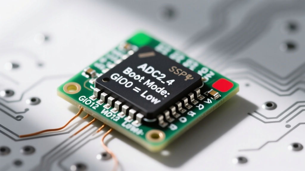
The most common point of failure for beginners learning to program ESP32 hardware is ignoring the strapping pins. During a power-on reset or wake-up from deep sleep, the ESP32 samples the logic levels of specific GPIO pins to determine its boot mode. If these pins are not in the correct state, the chip will fail to enter the UART bootloader, resulting in the dreaded 'Timed out waiting for packet header' error in the Arduino IDE.
| GPIO Pin | Function | Bootloader Mode (Required to Program) | Normal Execution Mode |
|---|---|---|---|
| GPIO0 | Boot Mode Select | Must be LOW (0) | HIGH (1) |
| GPIO2 | Boot Mode Select | Must be LOW (0) or Floating | HIGH (1) or Floating |
| GPIO12 | Flash Voltage Select | LOW (Selects 3.3V flash) | HIGH (Selects 1.8V flash) |
| GPIO15 | Boot Log Print | LOW (Silences boot logs) | HIGH (Prints boot logs to UART) |
Critical Failure Mode: If you connect a relay, an LED, or a pull-up resistor to GPIO12 and it pulls the pin HIGH during boot, the ESP32 will attempt to switch the internal SPI flash voltage regulator to 1.8V. Since most standard modules (like the WROOM-32) use 3.3V SPI flash, the chip will immediately brownout or fail to read the firmware, resulting in a continuous boot loop. Always consult the Espressif Bootloader Documentation before assigning strapping pins to peripheral hardware.
The Auto-Reset Circuit: DTR and RTS Mechanics
How does the Arduino IDE actually force GPIO0 LOW and trigger a reset without you physically pressing buttons on the development board? The answer lies in the USB-to-UART bridge IC (typically a CP2102N, CH340C, or FT232RL) and a clever transistor auto-reset circuit.
When the IDE initiates an upload, it manipulates the DTR (Data Terminal Ready) and RTS (Request to Send) serial control lines in a specific sequence:
- RTS goes LOW, DTR goes HIGH: This pulls the EN (Enable/Reset) pin LOW, resetting the ESP32, while simultaneously pulling GPIO0 LOW via a transistor bridge.
- RTS goes HIGH, DTR goes LOW: The EN pin is released (pulled HIGH via a 10k resistor), taking the chip out of reset. Because GPIO0 is still held LOW by the circuit, the bootloader detects the strapping condition and enters UART download mode.
- Both lines release: GPIO0 floats HIGH, and the newly flashed firmware begins execution.
If you are designing a custom PCB without the auto-reset circuit, you must manually hold the 'BOOT' button (GPIO0) down, press the 'EN' button (Reset), and then release the 'BOOT' button to force the chip into programming mode.
SPI Flash Memory Mapping and Partition Tables
When you compile a sketch, the resulting binary is not just dumped into a single block of memory. The ESP32 uses an external SPI flash chip (usually 4MB, 8MB, or 16MB) divided into a strict partition table. Understanding this layout is vital when you need to store large web servers, audio files, or machine learning models alongside your code.
A standard 'Default 4MB with spiffs' partition table looks like this:
- Bootloader (0x0000 - 0x8000): The primary ROM bootloader that initializes the hardware.
- Partition Table (0x8000 - 0x9000): The map telling the chip where everything else lives.
- NVS (0x9000 - 0xB000): Non-Volatile Storage. This is where the Wi-Fi manager stores SSID credentials and where the
Preferenceslibrary saves data. It survives OTA updates. - OTA Data (0xB000 - 0xD000): Tracks which application partition is currently active for Over-The-Air updates.
- App0 (0x10000 - 0x150000): The primary 1.2MB partition where your compiled Arduino sketch resides.
- App1 (0x150000 - 0x290000): The secondary 1.2MB partition used as a staging area for OTA firmware updates.
- SPIFFS (0x290000 - 0x3F0000): The remaining ~1.4MB formatted as a file system for storing HTML, CSS, images, or JSON configurations.
If your compiled code exceeds the 1.2MB App0 limit, you must use the Arduino IDE 'Partition Scheme' menu to select 'No OTA (2MB APP/2MB SPIFFS)', which sacrifices the ability to update firmware wirelessly in exchange for a massive 2MB application partition. For deep dives into custom memory layouts, review the official ESP-IDF Partition Table guide.
Toolchain Showdown: Arduino Core vs. ESP-IDF
Deciding how to program ESP32 devices depends entirely on your project requirements. The community is largely split between two primary toolchains.
| Feature | Arduino-ESP32 Core | Espressif ESP-IDF (C/C++) |
|---|---|---|
| Learning Curve | Low (Familiar IDE, simple API) | Steep (CMake, FreeRTOS, complex menus) |
| Hardware Access | Abstracted (AnalogWrite, Wire, SPI) | Direct (Register manipulation, LEDC, RMT) |
| Power Management | Limited (Basic deep sleep functions) | Granular (ULP coprocessor, dynamic clock scaling) |
| Best Use Case | Prototyping, hobbyist IoT, simple sensors | Commercial products, battery-operated devices, audio |
The Arduino-ESP32 Core GitHub repository is essentially a massive abstraction layer built on top of the ESP-IDF. While it makes blinking an LED or connecting to Wi-Fi trivial, it abstracts away the power-saving features of the ULP (Ultra-Low Power) coprocessor. If you are building a commercial, battery-powered sensor that must sleep for months, you will eventually need to transition to the native ESP-IDF environment.
Troubleshooting Common Upload Failures
Even with a firm grasp of the architecture, physical layer issues frequently prevent successful programming. Follow this diagnostic checklist when the IDE fails to connect:
1. The USB Cable Trap
Over 40% of 'dead' ESP32 boards are actually just charge-only USB cables. A charge-only cable lacks the D+ and D- data lines required for UART communication. Always verify your cable with a known-good device like a smartphone before assuming the CP2102 chip is fried.
2. Baud Rate Collisions
The Arduino IDE defaults to an upload speed of 921600 baud. While the ESP32 UART hardware can handle this, cheap USB-to-Serial adapters and long, unshielded USB cables often suffer from signal degradation at these frequencies, resulting in hash mismatch errors. Drop the upload speed to 115200 or 460800 in the IDE Tools menu to prioritize reliability over speed.
3. Driver Conflicts (CH340 vs CP2102)
Cloned development boards frequently use the CH340G or CH340C USB-to-UART chips to save costs. Windows and macOS do not always include native drivers for these ICs. If your board appears in the Device Manager as an 'Unknown Device' or throws a Code 10 error, you must manually download and install the signed CH340 drivers from the manufacturer's repository before the IDE will recognize the COM port.
Mastering how to program ESP32 hardware requires looking past the simplicity of the Arduino IDE and respecting the silicon underneath. By managing your strapping pins, understanding the SPI flash partitions, and utilizing the dual-core architecture effectively, you can build robust, commercial-grade IoT systems from your workbench.