
The Bottleneck in Standalone MCU Programming
Transitioning from a breadboard prototype to a custom PCB or small-batch production run introduces a significant workflow bottleneck: programming the standalone microcontroller. While the Arduino IDE is excellent for prototyping, relying on serial bootloaders for production is inefficient. It requires a USB-to-Serial adapter on every target board, consumes valuable flash memory, and adds boot delay. This is where mastering the Arduino ISP (In-System Programming) workflow becomes critical for any serious maker or hardware startup.
Using an Arduino as an ISP programmer allows you to bypass the serial bootloader entirely, flashing the hex file directly to the target MCU's memory via the SPI bus (MISO, MOSI, SCK, and RESET). However, the default out-of-the-box Arduino ISP experience is manual, slow, and prone to connection errors. In this guide, we will dissect how to optimize your Arduino ISP workflow for 2026, transforming a tedious manual process into a streamlined, semi-automated production pipeline using custom jigs, dedicated hardware, and command-line scripting.
Hardware Selection: Arduino as ISP vs. Dedicated Programmers
The first step in workflow optimization is evaluating your programming hardware. While the classic Arduino as ISP sketch turns a standard Uno into a programmer, it is not always the most efficient tool for batch flashing. Below is a comparison of common ISP hardware options available in 2026, analyzing their cost, speed, and workflow fit.
| Programmer Hardware | Approx. Cost (2026) | SPI Clock Speed | Workflow Fit & Reliability |
|---|---|---|---|
| Arduino Uno R3 (Running ArduinoISP sketch) | $27.00 (Official) | Fixed (approx. 125kHz) | Best for quick prototyping. Prone to auto-reset bugs without hardware mods. |
| Generic USBasp Clone | $4.00 - $8.00 | Jumper selectable (up to 1.5MHz) | Good for hobbyist batch runs. Firmware updates often required for modern AVRDude. |
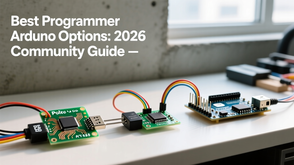
| Pololu USB AVR Programmer v2.1 | $11.95 | Configurable (up to 3MHz) | Professional small-batch. Highly reliable, acts as TTL serial bridge simultaneously. |
| Arduino Uno R4 Minima (Custom ISP Firmware) | $20.00 | High (Native USB speed) | Excellent for modern workflows, but requires community firmware for native ISP. |
For a true production workflow optimization, we highly recommend moving away from the standard Uno R3 running the default sketch and investing in a Pololu USB AVR Programmer v2.1. It eliminates the serial auto-reset capacitor issue inherent to the Uno R3, supports higher SPI clock speeds for faster flashing, and provides a stable 3.3V/5V VCC output to power your target board during programming.
Designing a Pogo-Pin Flashing Jig for Workflow Speed
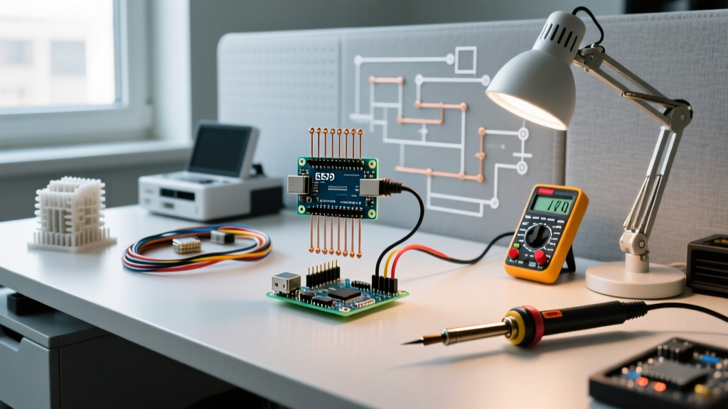
If you are programming more than ten boards, manually inserting and removing jumper wires into a 2x3 ICSP header will destroy your productivity and cause physical wear on the headers. The industry-standard solution is a 'bed of nails' or pogo-pin test jig. Designing a 3D-printed jig tailored to your PCB layout reduces programming time from 45 seconds per board to under 5 seconds.
Component Selection for the Jig
- Pogo Pins: Use P50-J1 spring-loaded pins. They feature a 0.68mm conical tip and a 75g spring force, which is ideal for standard 1.27mm pitch ICSP pads without damaging the PCB trace.
- Housing: Print the jig base in PETG or ABS. PLA deforms under the repeated friction and spring pressure of batch programming. Use a 0.2mm layer height and 100% infill for the pin-alignment plate to ensure zero tolerancing drift.
- Alignment: Incorporate two non-conductive alignment pegs (using 2mm dowel pins) that mate with mounting holes on your target PCB. This prevents the pogo pins from slipping and shorting VCC to GND.
Wiring the Jig to the ISP Programmer
- Solder the P50-J1 pins to a custom breakout board or directly to a ribbon cable.
- Map the standard 2x3 AVR ICSP pinout: Pin 1 (MISO), Pin 2 (VCC), Pin 3 (SCK), Pin 4 (MOSI), Pin 5 (RESET), Pin 6 (GND).
- Add a 100nF decoupling capacitor directly across the VCC and GND lines inside the jig housing to suppress voltage spikes during the initial MCU power-on surge.
Automating the Software Pipeline with Avrdude Scripts
The Arduino IDE GUI is a massive bottleneck for batch programming. Clicking 'Upload', waiting for the compilation, and monitoring the serial output adds unnecessary overhead. To optimize your workflow, you must bypass the IDE and interface directly with AVRDude, the underlying command-line utility that handles the actual ISP communication.
By pre-compiling your sketch and exporting the compiled binary (.hex file), you can write a simple batch script (.bat for Windows or .sh for Linux/macOS) to flash the board and set the fuse bits in a single keystroke.
Example Windows Batch Script for ATmega328P
@echo off
echo Flashing ATmega328P via Arduino ISP...
avrdude -c arduino -p m328p -P COM3 -b 19200 -U flash:w:firmware_v2.hex:i -U efuse:w:0xFD:m -U hfuse:w:0xDE:m -U lfuse:w:0xFF:m
if %errorlevel% == 0 (
    echo SUCCESS: Board programmed and fuses set.
    color 0A
) else (
    echo ERROR: Programming failed. Check connections.
    color 0C
)
pause
Note: The fuse bytes in this script (0xFD, 0xDE, 0xFF) configure the ATmega328P for a 16MHz external crystal oscillator with the brown-out detector enabled at 2.7V. Always verify fuse calculations using an Arduino ISP fuse calculator before executing, as incorrect fuse bits can brick the MCU by disabling the reset pin or selecting a non-existent clock source.
Troubleshooting Common Arduino ISP Failure Modes
Even with an optimized hardware and software pipeline, ISP programming introduces specific failure modes that can halt a production run. Understanding these edge cases is vital for maintaining workflow momentum.
The Auto-Reset Capacitor Bug (Uno R3 Specific)
If you are using an Arduino Uno R3 as your ISP programmer, you will frequently encounter the avrdude: stk500_getsync() attempt 1 of 10: not in sync error. This occurs because the Uno R3 has a 0.1µF capacitor on the DTR line designed to auto-reset the board when the serial port opens. When AVRDude opens the COM port, it resets the programmer board itself, knocking it out of ISP mode before it can talk to the target.
The 10µF Hardware Fix: To disable this auto-reset behavior, plug a 10µF electrolytic capacitor between the RESET and GND pins on the programmer Arduino. Ensure the capacitor's cathode (negative stripe) is connected to GND. This absorbs the DTR voltage spike, keeping the programmer awake. Note: The Arduino Uno R4 Minima does not suffer from this hardware flaw due to its redesigned USB-to-Serial architecture.
Target Board Brown-Out During Flashing
When programming an ATtiny85 or a bare ATmega328P, the target board draws power directly from the programmer's VCC pin. Standard USB 2.0 ports limit current to 500mA, and the onboard 5V regulator of a clone Arduino Uno can often only supply 200mA safely. If your target PCB includes power-hungry peripherals (like an nRF24L01 radio module or a string of WS2812B LEDs) connected to the same VCC rail, the voltage will sag during the flash write cycle, causing the MCU to brown-out and the ISP handshake to fail.
Optimization: Never rely on the programmer to power a fully populated target board. Design your PCB with a 'VCC_PROG' jumper or use a pogo-pin jig that injects power from a dedicated external bench supply (set to 5.0V, 2A limit) rather than routing power through the ISP cable.
Clock Speed Mismatches and the 'Slow SCK' Rule
AVRDude communicates via the SPI bus. The SPI clock speed must be strictly less than 1/4th of the target MCU's CPU clock frequency. If you are flashing a fresh ATmega328P straight from the factory, it runs on its internal 1MHz oscillator by default. If your Arduino ISP sketch attempts to communicate at a standard 125kHz or 250kHz SPI clock, the math works out. However, if you are using a high-speed dedicated programmer attempting a 1MHz SPI clock, the programming will fail because the MCU cannot process the bits fast enough.
Optimization: Always include the -B flag in your AVRDude command to manually set the bit clock period. For a fresh 1MHz factory chip, use -B 32 (which yields a safe ~31kHz SPI clock). Once the fuses are written to enable a 16MHz external crystal, you can drop the -B flag or set it to -B 1 for high-speed flashing on subsequent runs.
Summary Checklist for Production
To finalize your workflow optimization, ensure your programming station meets these criteria before starting a batch run:
- [ ] Hardware upgraded to a dedicated ISP programmer (e.g., Pololu v2.1) or Uno R3 modified with a 10µF reset capacitor.
- [ ] 3D-printed PETG pogo-pin jig assembled with P50-J1 pins and alignment dowels.
- [ ] Target PCB powered by an external supply, not the ISP header VCC.
- [ ] AVRDude batch script configured with correct COM port, hex file path, and verified fuse bytes.
- [ ] Bit-clock (
-B) adjusted for the initial factory state of the target MCUs.
By treating the Arduino ISP process not as a software feature, but as a physical manufacturing step, you eliminate the friction of manual wiring and GUI compiling. This optimized workflow scales effortlessly from a single weekend prototype to a 500-unit Kickstarter production run.