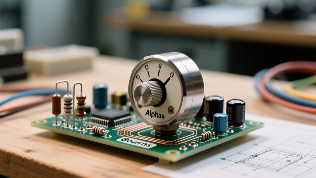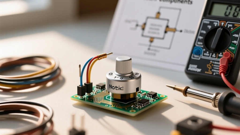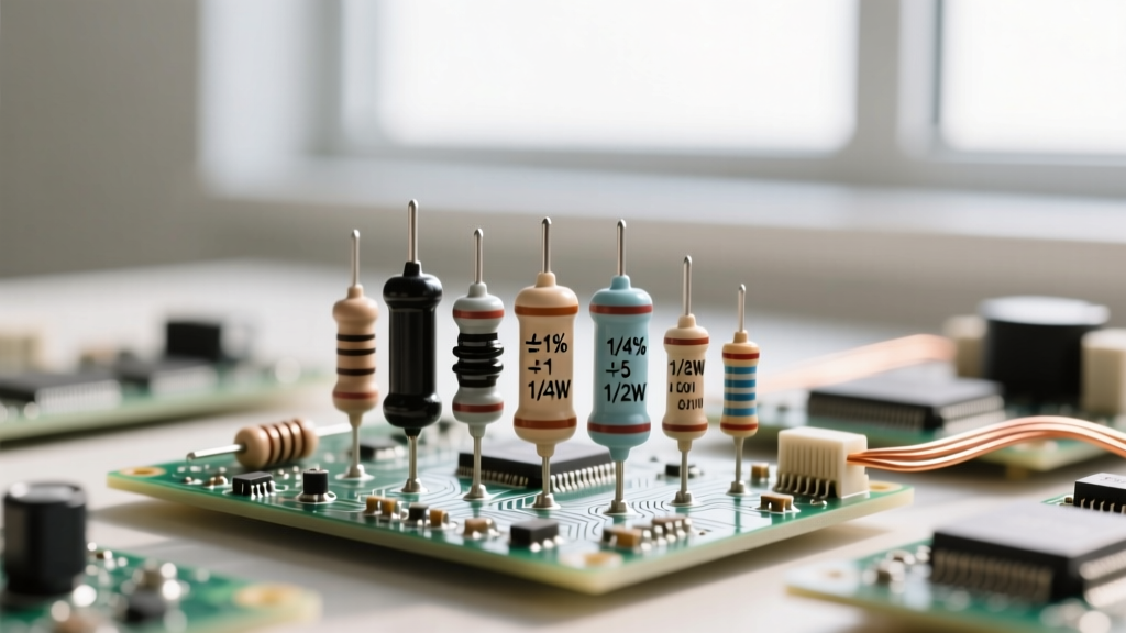

The Disconnect Between Schematics and Procurement
For electronics engineers and DIY prototypers, the schematic is the ultimate source of truth. However, a common point of failure in hardware development occurs at the intersection of schematic design and physical component procurement. Nowhere is this more evident than with the potentiometer schematic symbol. A simple variable resistor symbol on a CAD sheet rarely conveys the complex mechanical, electrical, and material specifications required to source the correct physical component. Misinterpreting these symbols—or failing to annotate them with critical implicit data—leads to procuring parts with the wrong taper, incompatible shaft dimensions, or inadequate power ratings. This guide bridges the gap between schematic notation and the real-world bill of materials (BOM), ensuring you select the exact potentiometer your circuit demands.
Anatomy of the Potentiometer Schematic Symbol
At its core, a potentiometer is a three-terminal resistor with a continuously adjustable tapping point (the wiper). When reviewing schematics, you will encounter two primary international standards for depicting this component:
IEEE/ANSI vs. IEC Notations
In North America, the IEEE/ANSI Y32.2 standard represents the fixed resistance track as a zigzag line (similar to a standard resistor), with an arrow pointing into the center to denote the wiper terminal. Conversely, the IEC (International Electrotechnical Commission) standard, widely used in Europe and modern global EDA tools, depicts the resistance track as a hollow rectangle with an arrow intersecting it. Regardless of the regional standard, the arrow always represents the wiper. If the arrow is drawn with a line crossing it or terminating in a diagonal slash, it indicates a variable resistor (rheostat) configuration where the wiper is internally or externally tied to one of the end terminals.
Mapping Taper Symbols to Physical Buying Specs
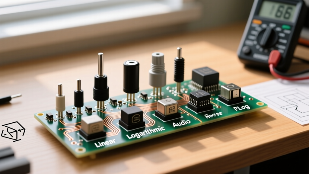
The most frequent procurement error stems from the taper—the mathematical relationship between the mechanical rotation of the shaft and the electrical resistance output. Schematics often omit taper details, or use obscure shorthand. Understanding these notations is critical for sourcing the right part from manufacturers like Bourns, Alps, or TT Electronics.
Linear Taper (B-Taper)
Schematic Notation: Often marked with a "B" or a straight diagonal graph line next to the symbol.
Buying Spec: The resistance changes in direct proportion to the shaft angle. At 50% mechanical rotation, you get exactly 50% of the total resistance.
Application: Voltage dividers, sensor calibration, motor speed controls, and equalizer circuits.
Example Part: Bourns 3590 series (Precision Wirewound) or standard carbon film panel pots.
Audio/Logarithmic Taper (A-Taper)
Schematic Notation: Marked with an "A" or an exponential curve graph.
Buying Spec: The resistance changes logarithmically. At 50% rotation, the resistance is typically only 10% to 15% of the total value. This compensates for the human ear's non-linear perception of loudness.
Application: Audio volume controls.
Example Part: Alps RK09 series or Bourns PTD90 series conductive plastic audio pots.
Reverse Logarithmic (C-Taper)
Schematic Notation: Marked with a "C" or an inverted exponential curve.
Buying Spec: The inverse of the audio taper; resistance increases sharply at the beginning of the rotation. Used in specific audio fade circuits and specialized instrumentation.
Trimpots vs. Panel Mounts: Symbol Distinctions
Schematics occasionally differentiate between user-facing panel potentiometers and internal calibration trimmers (trimpots). A standard potentiometer symbol implies a panel-mount component with a shaft and bushing. However, if the symbol is enclosed in a small box, or features a tiny screwdriver icon next to the wiper arrow, it designates a trimpot. When sourcing trimpots, you must decide on the physical orientation based on your PCB layout:
- Top-Adjust (e.g., Bourns 3296W): The adjustment screw faces upward, parallel to the component footprint. Ideal for boards with ample vertical clearance.
- Side-Adjust (e.g., Bourns 3296X): The screw faces sideways, perpendicular to the PCB. Essential for densely packed boards where vertical access is blocked by adjacent components or enclosures.
Material Selection: Beyond the Schematic
The schematic symbol will never tell you what the resistive track is made of, yet this dictates the component's lifespan, noise floor, and environmental resilience. As a buyer, you must append these material specifications to your BOM based on the circuit's function.
Carbon Composition
The most common and economical material. It offers a wide resistance range but suffers from high rotational noise (CRV - Contact Resistance Variation) and poor long-term stability due to mechanical wear. Buy these only for non-critical, low-budget consumer applications.
Cermet (Ceramic/Metal)
Standard for multi-turn precision trimmers. Cermet elements withstand high soldering temperatures and offer excellent stability over time and temperature variations. They are the mandatory choice for precision analog calibration circuits.
Conductive Plastic
The gold standard for high-end audio faders and studio equipment. Conductive plastic offers an incredibly smooth wiper action, ultra-low noise, and a lifespan exceeding 1,000,000 cycles. If your schematic involves high-fidelity audio mixing, specify conductive plastic elements.
Schematic Symbol to Real-World BOM Matrix
| Schematic Symbol Feature | Procurement Specification | Real-World Example Part |
|---|---|---|
| Standard 3-Terminal (IEEE Zigzag) | Single-Gang Panel Mount, Specify Taper & Shaft Type | Bourns 510 Series (10k Ohm, B-Taper, Knurled Shaft) |
| Two Stacked Symbols (Shared Shaft) | Dual-Gang Potentiometer (Used for Stereo Audio) | Alps RD7 Series (Dual 100k Ohm, A-Taper) |
| Box Enclosure with Screwdriver | Multi-Turn Cermet Trimmer, Specify Top/Side Adjust | Bourns 3296W-1-103LF (10k Ohm, 25-Turn, Top Adjust) |
| Wiper Tied to End Terminal | Rheostat Configuration (Buy 3-Terminal & Wire as 2) | Vishay 534 Series (Wirewound, High Power 2W) |
| Linear Slider Symbol (Straight Line) | Slide Potentiometer, Specify Travel Length (e.g., 100mm) | Bourns PTB0143 (10k Ohm, Audio Taper, 100mm Travel) |
Critical Purchasing Parameters Ignored by Symbols
When translating a potentiometer schematic symbol into a purchase order, relying solely on the resistance value (e.g., 10kΩ) is a recipe for mechanical and electrical failure. You must define the following parameters in your procurement notes:
1. Mechanical Rotation Angle
Most standard rotary pots offer 300° of mechanical rotation. However, precision servos and specific instrumentation may require 350° or continuous rotation (which lacks mechanical end-stops and requires a specialized hybrid or conductive plastic element without dead zones).
2. Shaft and Bushing Dimensions
A schematic will not tell you if the knob will fit the shaft. Standard panel pots typically use a 6mm (1/4 inch) shaft. You must specify whether you need a round shaft (requires a setscrew knob), a D-shaft (prevents slipping), or a split knurled shaft (standard for push-on plastic or aluminum knobs). Furthermore, the bushing thread (commonly 3/8"-32 UNEF in the US, or M7/M9 metric in Europe) must match your enclosure's mounting hole.
3. Power Rating and Voltage Limits
Standard carbon panel pots are typically rated for 0.125W to 0.5W. If your schematic places the potentiometer across a high-current power supply or uses it as a high-power rheostat for motor control, a standard part will overheat and fail catastrophically. For high-power applications, you must source wirewound potentiometers (like the Vishay 534 series) rated for 2W to 5W, complete with heat-dissipating metal housings.
Expert Procurement Tip: Never attempt to source a dedicated 2-terminal rheostat for modern prototyping. They are largely obsolete, carry massive price premiums, and have limited resistance ranges. Instead, purchase a standard 3-terminal potentiometer and wire the wiper to one of the outer terminals on your PCB or breadboard. This achieves the exact same variable resistance function while keeping your BOM costs low and lead times short.
Avoiding Wiper Noise and Contact Failures
When a schematic features a potentiometer in a high-gain audio preamp or a sensitive DC measurement loop, the physical quality of the wiper contact becomes paramount. All potentiometers exhibit some degree of Contact Resistance Variation (CRV)—a momentary spike in resistance when the wiper moves across the track. In cheap carbon pots, this manifests as audible "scratchiness" in audio circuits or voltage spikes in sensor arrays.
To mitigate this, consult resources like the comprehensive guides on All About Circuits - Potentiometers, which detail the physics of wiper contact. For critical designs, specify pots with "make-before-break" wiper contacts or opt for Bourns Potentiometers featuring multi-finger wiper designs that ensure continuous electrical contact even if one finger encounters a microscopic void in the resistive track. Furthermore, implementing a simple software debouncing algorithm or a hardware low-pass capacitor across the wiper and ground can salvage a circuit if budget constraints force the use of lower-grade carbon elements.
Finalizing Your BOM
The potentiometer schematic symbol is merely the starting point of your design intent. By systematically decoding the implicit requirements of taper, material, gang configuration, and mechanical footprint, you transform a generic schematic icon into a highly specified, reliable physical component. Always cross-reference your schematic annotations with the manufacturer's datasheet, paying special attention to the tolerance (typically ±20% for carbon, ±10% for cermet) and the operational temperature range. Mastering this translation process ensures your prototype not only functions on the breadboard but survives the transition to a robust, manufacturable final product.