
Unboxing the potentiometer: What Exactly Is It?
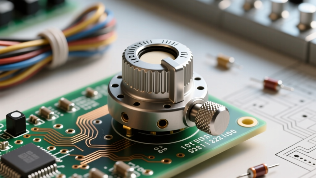
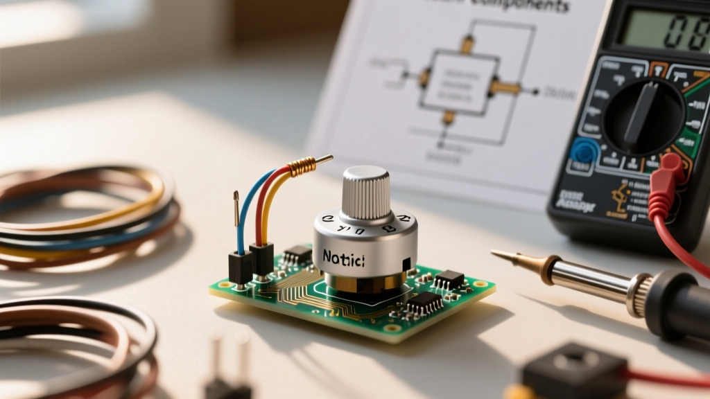
When you first open your beginner electronics kit, nestled among the LEDs, jumper wires, and resistors, you will inevitably find a small, circular component with three metal pins protruding from the bottom and a rotating shaft on top. This is the potentiometer (often abbreviated as a "pot"). For a beginner, it is the gateway to analog control in a digital world. Whether you are dimming an LED, controlling the speed of a DC motor, or building a MIDI controller, understanding how to harness this variable resistor is a fundamental rite of passage.
In most standard Arduino or Raspberry Pi starter kits, the included potentiometer is typically a 10-kilo-ohm (10KΩ) linear panel-mount model, such as the Alpha RD9 series or a generic equivalent. But how does it actually work, and why does it have three pins instead of two like a standard resistor?
The Anatomy of a Standard Panel Pot
At its core, a potentiometer is a mechanical voltage divider. Inside the metal or plastic casing lies a resistive element—usually a carbon composition track or a cermet (ceramic-metal) film. A spring-loaded metal contact called the wiper glides along this track as you turn the shaft.
- Pin 1 (Clockwise Terminal): Connects to one end of the resistive track.
- Pin 2 (The Wiper): The middle pin that moves along the track, outputting the variable voltage.
- Pin 3 (Counter-Clockwise Terminal): Connects to the opposite end of the resistive track.
By applying a reference voltage (e.g., 5V) across Pins 1 and 3, the wiper (Pin 2) taps off a proportional voltage based on its physical position. If the wiper is exactly in the middle of a 10KΩ track, it outputs 2.5V.
Decoding the Markings: Linear vs. Logarithmic Tapers
Flip the potentiometer over, and you will see alphanumeric codes stamped on the back, such as B10K or A10K. The number indicates the total resistance (10,000 ohms), but the letter denotes the taper—the mathematical curve of the resistance change relative to the shaft rotation.
Expert Insight: Never use an Audio (Logarithmic) taper potentiometer for microcontroller analog inputs unless you are specifically compensating for human hearing perception in an audio circuit. The non-linear voltage output will map poorly to your microcontroller's Analog-to-Digital Converter (ADC).
Here is a breakdown of the two most common tapers found in electronics:
- Linear Taper (Marked with 'B', e.g., B10K): The resistance changes at a constant rate. Turning the shaft 50% yields exactly 50% of the total resistance (and 50% of the voltage). This is the standard for microcontroller inputs, motor speed controls, and sensor calibration.
- Logarithmic/Audio Taper (Marked with 'A', e.g., A10K): The resistance changes slowly at first, then rapidly. This mimics the logarithmic way human ears perceive volume. This is strictly used in audio amplifiers and tone circuits.
How to Wire the potentiometer to a Microcontroller
The most common beginner project involving the potentiometer is reading its position using a microcontroller's ADC (Analog-to-Digital Converter). Let's look at how to wire it to an Arduino Uno.
The Voltage Divider Configuration
To read the pot, you must wire it as a voltage divider. According to SparkFun's guide on voltage dividers, the output voltage (Vout) is calculated as:
Vout = Vin × (R2 / (R1 + R2))
Here is the exact wiring schematic for a standard 10KΩ B-taper pot:
- Left Pin (Terminal 1): Connect to GND (Ground) on the Arduino.
- Middle Pin (Wiper): Connect to an analog input pin (e.g., A0).
- Right Pin (Terminal 3): Connect to 5V (or 3.3V, depending on your board's logic level).
Note: If you find that turning the knob clockwise decreases your sensor reading instead of increasing it, simply swap the GND and 5V wires on the outer pins. The wiper pin must always remain connected to the ADC.
Once wired, you can use the standard Arduino AnalogReadSerial function to map the 0-5V range into a 10-bit integer (0 to 1023). This allows your code to trigger events based on physical knob positions.
Common Beginner Mistakes and Failure Modes
While the potentiometer is robust, beginners often encounter erratic behavior when prototyping on breadboards. Below is a troubleshooting matrix to help you diagnose common issues.
| Symptom | Probable Cause | Engineering Fix |
|---|---|---|
| ADC readings jump wildly (e.g., 512 to 518) | Thermal noise or high-impedance ADC sampling capacitor charge time. | Add a 0.1µF ceramic capacitor between the Wiper pin and GND to filter high-frequency noise. |
| Readings max out at 1023 regardless of position | Wired as a variable resistor (rheostat) instead of a voltage divider, or wiper pin is floating. | Ensure all three pins are connected. Outer pins to VCC/GND, middle to ADC. |
| Physical "scratchy" noise in audio circuits | Oxidation or dust on the carbon track causing intermittent wiper contact resistance. | Spray the internal slot with DeoxIT D5 contact cleaner and rotate the shaft 20 times to clean the track. |
| Knob feels loose, value doesn't change at extremes | The D-shaft plastic knob has cracked, or the internal mechanical stop has sheared off due to over-rotation. | Replace the potentiometer. Never force a pot past its mechanical detents (usually ~270° to 300°). |
Upgrading Your Kit: Beyond the Basic 10K Pot
Once you have mastered the standard single-turn panel potentiometer, your projects will eventually demand more precision or digital control. As outlined in comprehensive All About Circuits literature on variable resistors, understanding the broader family of pots is crucial for intermediate prototyping.
Multi-Turn Precision Trimmers
If you are building a DIY bench power supply or a sensor calibration circuit, a standard 270-degree knob lacks the resolution needed for fine-tuning. Enter the multi-turn trimmer potentiometer (such as the Bourns 3590 series). These require 10 to 25 full rotations of a precision screw to traverse the entire resistive track. They are typically cermet-based, offering excellent temperature stability and a long operational life, though they are meant for "set-and-forget" calibration rather than continuous user interaction.
Digital Potentiometers (Digipots)
Mechanical pots suffer from physical wear, wiper bounce, and require manual intervention. When you need software-defined resistance—such as programmable gain amplifiers or digital volume controls—you upgrade to a digital potentiometer like the Microchip MCP41010. These ICs use an internal resistor ladder and MOSFET switches to simulate a wiper position, controlled via SPI or I2C protocols. While they lack the high current-handling capabilities of a carbon-track pot, they are immune to mechanical vibration and can be automated by your microcontroller.
Final Thoughts for the Prototyper
The potentiometer is deceptively simple, yet it bridges the gap between the physical and digital realms of electronics. By understanding the difference between linear and logarithmic tapers, correctly wiring the voltage divider, and knowing how to filter wiper noise, you elevate your projects from erratic breadboard experiments to reliable, responsive prototypes. Keep experimenting with different resistance values—try a 100KΩ pot for low-power battery circuits, or a 1KΩ pot for driving higher-current analog loads—and let your component kit be the foundation of your embedded systems journey.