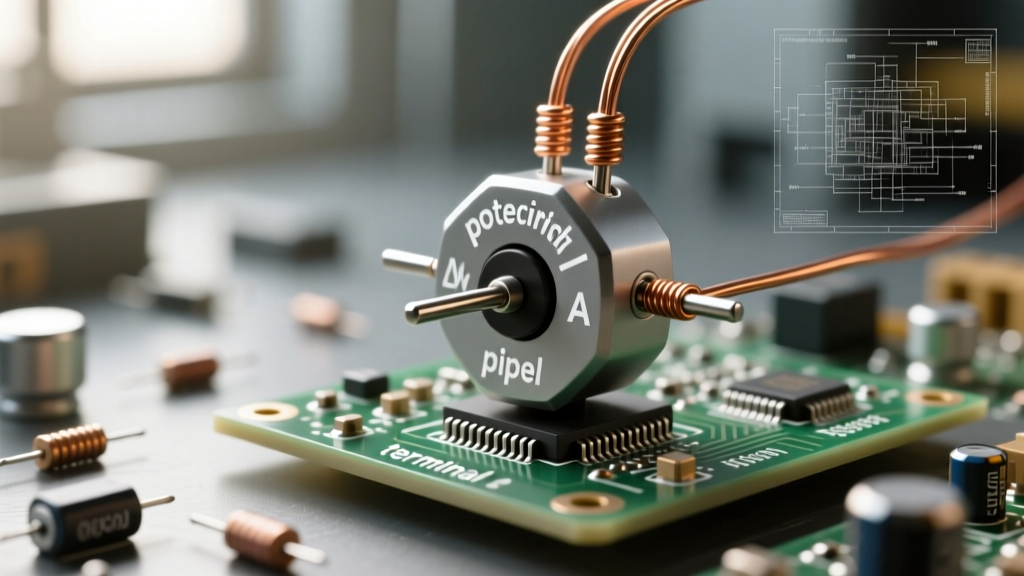

Every DIY electronics workbench eventually accumulates a tangled bin of three-terminal components. But when you reach into that bin, do you truly know which one to grab? If you have ever found yourself asking, "potentiometer what does it do?" while staring at a schematic, you are not alone. While fundamentally a variable resistor, the modern potentiometer is a complex electromechanical transducer. Selecting the wrong type can lead to scratchy audio, jittery microcontroller readings, or premature component failure.
This comprehensive buyer's guide bridges the gap between basic theory and practical procurement, helping you select the exact component for your next prototype or production run.
The Core Function: What Does a Potentiometer Actually Do?
At its most fundamental level, a potentiometer (often called a "pot") is a three-terminal resistor with a sliding or rotating contact that forms an adjustable voltage divider. According to the foundational tutorials on All About Circuits, the device operates on a simple principle: a resistive element is connected across a voltage source, and a wiper taps into a specific point along that element to output a fraction of the total voltage.
Voltage Divider vs. Rheostat Configuration
Understanding how you wire the potentiometer dictates what it does in your circuit:
- Voltage Divider (3-Terminal): All three pins are used. The outer pins connect to VCC and GND, while the center wiper pin provides a variable voltage output ($V_{out}$). This is used for volume controls, position sensing, and reference voltage generation.
- Rheostat (2-Terminal): Only the wiper and one outer pin are used. This configuration varies the current or total resistance in a series circuit. It is commonly used for motor speed controls or simple LED dimming, though it is less efficient than modern PWM solutions.
Matching the Taper to Your Application
The "taper" refers to the mathematical relationship between the physical position of the wiper and the resistance ratio. Buying a pot without checking the taper is the most common mistake beginners make.
Linear Taper (B-Taper)
In a linear potentiometer, the resistance changes at a constant rate relative to the shaft rotation. If you turn the shaft to the 50% mark, the resistance between the wiper and ground is exactly 50% of the total resistance. Best for: Position sensors, joystick controllers, LED dimming, and any application where the microcontroller needs a direct, proportional analog reading.
Logarithmic / Audio Taper (A-Taper)
Human hearing does not perceive volume linearly; it follows a logarithmic curve based on the Weber-Fechner law. An audio taper potentiometer mimics this perception. At the physical midpoint of the shaft rotation, the resistance is typically only 10% to 20% of the total value. Best for: Audio amplifiers, mixer consoles, and tone controls. Using a linear pot for audio volume will result in a knob that does "nothing" for the first 70% of its rotation, then suddenly spikes in volume.
Reverse Logarithmic (C-Taper)
This is the inverse of the audio taper, where the resistance changes rapidly at the beginning of the rotation and levels off. Best for: Specialized audio pan controls and certain feedback networks in analog synthesizers.
Decoding Resistive Element Materials
When browsing catalogs from manufacturers like Bourns or Vishay, the material of the resistive track dictates the component's lifespan, noise floor, and power handling.
| Material | Resolution | Lifespan (Cycles) | Typical Use Case | Notable Drawback |
|---|---|---|---|---|
| Carbon Film | Good | 15,000 - 50,000 | Consumer audio, cheap DIY kits | High thermal noise, wears down over time causing "scratchy" sounds. |
| Cermet | Excellent | 200 - 1,000 (Trimmers) | PCB trimmers, calibration circuits | Not meant for continuous user adjustment; brittle. |
| Wirewound | Discrete Steps | 500,000+ | High-power rheostats, precision dials | Inductive reactance at high frequencies; wiper can bounce between windings. |
| Conductive Plastic | Infinite | 1,000,000+ | High-end audio, industrial joysticks | Higher cost; lower power dissipation limits. |
Mechanical Form Factors and Mounting Styles
What does a potentiometer do if it does not fit your enclosure? The physical form factor is just as critical as the electrical specifications.
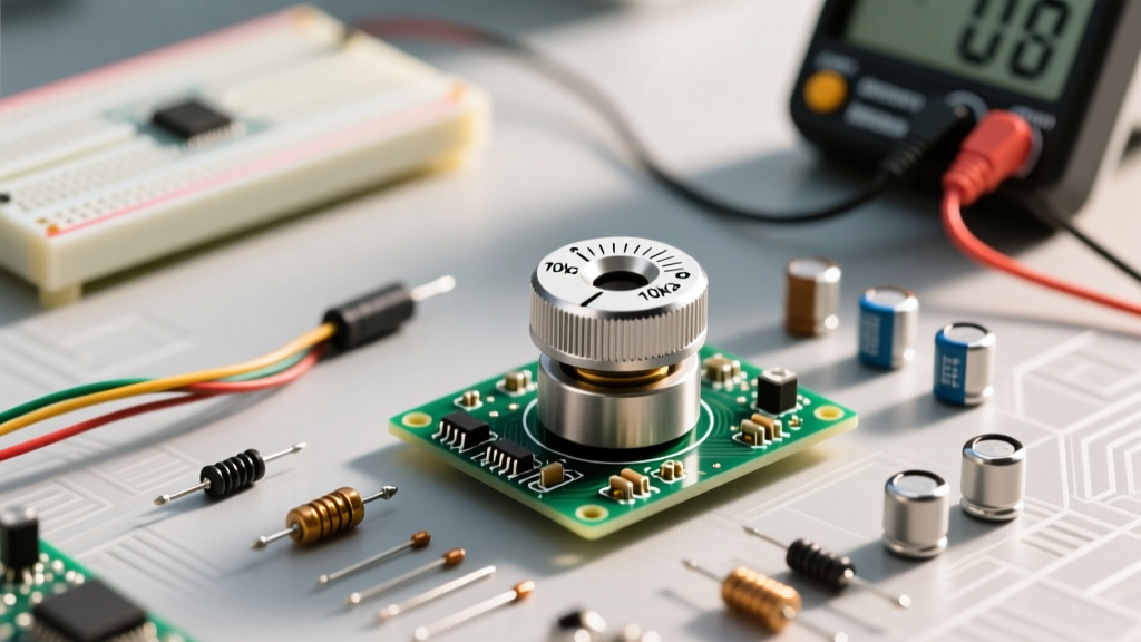
- Panel Mount (Rotary): The classic shaft-mounted pot (e.g., Alpha RD901F series). They feature a threaded bushing for secure mounting to an aluminum or plastic faceplate. Look for D-shaft or knurled split-shaft ends depending on your knob choice.
- Slide Potentiometers: Used heavily in audio mixing desks and lighting consoles. The Alps Alpine RS60 series is an industry standard here, offering long travel distances (up to 100mm) for precise visual and physical fader alignment.
- PCB Trimmers (Trimpots): Designed for "set-and-forget" calibration. The Bourns 3296 series is legendary in prototyping. Be careful to order the correct orientation: the 3296W is top-adjust, while the 3296Y is side-adjust. Multi-turn versions (usually 25 turns) allow for microscopic calibration adjustments.
Quick-Reference Buyer's Matrix
Use this decision framework to quickly narrow down your selection based on your project's primary goal:
- Arduino/MCU Sensor Input: 10KΩ, Linear (B-Taper), Carbon or Conductive Plastic, Panel Mount.
- Guitar Amplifier Volume: 250KΩ or 500KΩ, Logarithmic (A-Taper), Carbon Film, Panel Mount.
- Op-Amp Gain Calibration: 10KΩ to 50KΩ, Linear, Cermet Multi-Turn Trimmer (e.g., Bourns 3296W).
- High-Current Motor Control: 100Ω, Linear, Wirewound (Rheostat config), High Wattage (5W+).
Common Prototyping Pitfalls and Failure Modes
Expert Insight: Never use a 1MΩ potentiometer to drive an Arduino analog input without a buffer. The internal sample-and-hold capacitor of the ATmega328P ADC requires a source impedance of 10KΩ or less to charge fully before the conversion cycle ends. High-resistance pots will result in wildly fluctuating, inaccurate readings.
The Loading Effect
A potentiometer only outputs the theoretical voltage calculated by the divider equation if the load connected to the wiper has infinite impedance. In reality, your microcontroller, amplifier, or oscilloscope has a finite input impedance. If the load impedance is not at least 10 to 100 times greater than the potentiometer's total resistance, the output curve will distort, bowing away from the ideal linear or logarithmic path. Always design your subsequent stage with high-impedance buffer op-amps if you must use high-value pots.
Wiper Lift-Off and Contact Noise
In carbon film and wirewound pots, physical vibration or mechanical wear can cause the wiper to momentarily lose contact with the resistive track. In a voltage divider circuit, this momentary "open" state causes the output voltage to spike to the rail or drop to zero, resulting in loud pops in audio circuits or catastrophic control spikes in motor drivers. To mitigate this, critical systems should use conductive plastic elements or implement software debouncing and clamping algorithms in the microcontroller firmware.
Thermal Drift
If you are using a potentiometer in a high-temperature environment (such as near a power supply transformer or inside an automotive dashboard), check the Temperature Coefficient of Resistance (TCR). Cermet and wirewound elements generally offer superior thermal stability (often ±100 ppm/°C) compared to carbon film (which can exceed ±500 ppm/°C).
Final Thoughts on Procurement
Understanding "potentiometer what does it do" is only the first step. The true mark of an experienced hardware designer is knowing which physical construction, resistive material, and taper profile will survive the specific demands of the end-user environment. By matching the taper to human perception (or machine logic), selecting the correct element material for the required lifecycle, and respecting impedance loading rules, you will eliminate an entire class of analog noise and calibration headaches from your prototyping workflow.