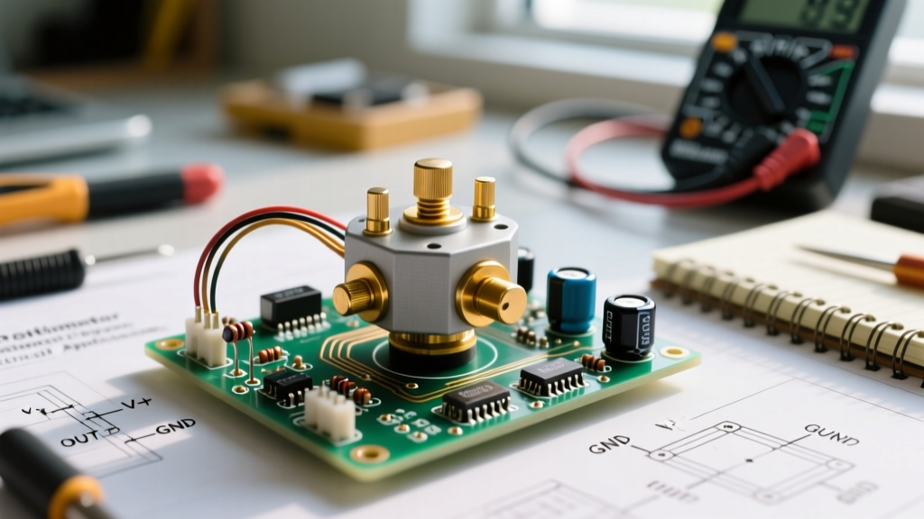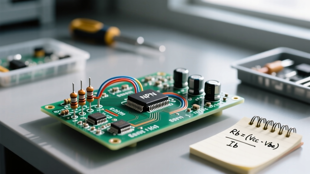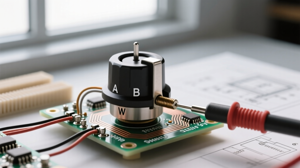

When hobbyists and engineers search for a potentiometer DC solution, they are usually trying to solve one of two problems: dividing a DC voltage for an analog reference signal, or controlling the power delivered to a DC load like a motor, LED array, or heating element. While a standard analog potentiometer seems like the obvious choice, applying it directly to DC power circuits is one of the most common—and destructive—mistakes in electronics prototyping.
In this guide, we will deconstruct the thermal and electrical limitations of analog potentiometers in DC circuits. More importantly, we will compare the most effective alternatives—including digital potentiometers, Pulse Width Modulation (PWM) switching, and DC-DC buck converters—so you can choose the right architecture for your specific prototyping scenario.
The Thermal Trap: Why Standard Pots Fail in DC Power Circuits
The fundamental misunderstanding of the analog potentiometer is treating it as a variable power resistor (rheostat) rather than a voltage divider. When you wire a potentiometer in series with a DC load to control current, you are forcing the component to dissipate the unused energy as heat.
Calculating the Wiper Current Limit
Consider a standard Bourns 3296W cermet trimpot. It has a maximum power rating of 0.5W. If you use a 100Ω version to control a 12V DC fan, the maximum continuous current it can handle is dictated by the formula P = I²R.
- I_max = √(0.5W / 100Ω) = 70.7mA
If your DC fan draws 200mA, the wiper will exceed its thermal limit. The carbon or cermet track will overheat, leading to localized melting, wiper arcing, and ultimately an open-circuit failure. This is known as the 'magic smoke' failure mode, and it is entirely avoidable by selecting the correct alternative.
Evaluating the Top Alternatives for DC Regulation
To safely control DC signals or DC power, we must decouple the control mechanism from the power path. Here are the three primary alternatives to using a raw analog potentiometer for DC control.
Alternative 1: Digital Potentiometers (Digipots)
Digital potentiometers, such as the Microchip MCP41050 or the Analog Devices AD5292, replace the mechanical wiper with an array of CMOS switches and resistors. They are controlled via SPI or I2C protocols.
According to Analog Devices, digipots are exceptional for programmable DC voltage biasing, active filter tuning, and sensor calibration. However, they are strictly signal-level components. The wiper pins on a typical digipot can only handle 1mA to 5mA of continuous DC current. If you need to set a precise DC reference voltage for an op-amp or an ADC, a digipot is the superior alternative. If you are trying to dim a 12V LED strip, a digipot will instantly fry its internal CMOS switches.
Alternative 2: PWM Switching via Logic-Level MOSFETs
For DC power control—such as motor speed regulation, LED dimming, or heating element control—Pulse Width Modulation (PWM) is the undisputed industry standard. Instead of dropping voltage across a resistive element, a microcontroller or 555-timer generates a high-frequency square wave (typically 1kHz to 20kHz) that switches a logic-level MOSFET (like the IRLZ44N) on and off.
As detailed in the SparkFun PWM Tutorial, the load experiences the average DC voltage based on the duty cycle. Because the MOSFET operates in either the fully-on (saturation) or fully-off (cutoff) region, power dissipation is minimal. An IRLZ44N has an R_DS(on) of just 22mΩ. At 10 Amps, it dissipates only 2.2W, easily managed with a small heatsink, compared to the hundreds of watts a theoretical analog rheostat would need to dissipate.
Alternative 3: DC-DC Buck Converters with Trim Feedback
If your application requires actual DC voltage step-down (rather than rapid switching), a switching regulator like the LM2596 is required. In this architecture, a small analog potentiometer (e.g., 10kΩ) is used safely in the feedback loop of the buck converter. The pot carries virtually zero current (only the microamp-level input bias current of the error amplifier), while the converter's inductor and switching diode handle the heavy DC load efficiently.
Component Comparison Matrix
The following table breaks down the electrical characteristics and ideal use cases for each potentiometer DC alternative.
| Feature | Analog Pot (Bourns 3296) | Digital Pot (MCP41050) | PWM + MOSFET (IRLZ44N) | DC-DC Buck (LM2596) |
|---|---|---|---|---|
| Max Wiper/Load Current | ~70mA (100Ω) | ~1mA (Signal only) | 47A (Continuous) | 3A (Output rail) |
| Power Dissipation | High (Inefficient) | Negligible | Very Low | Low (85% Efficiency) |
| Control Interface | Mechanical Shaft | SPI / I2C Digital | Digital PWM Signal | Analog Feedback Loop |
| Output Signal Type | True DC Voltage | True DC Voltage | High-Freq Square Wave | True DC Voltage |
| Best Application | Manual Signal Trimming | Automated Calibration | Motors, LEDs, Heaters | Variable DC Power Rails |
Application-Specific Decision Framework
Choosing the right architecture depends entirely on the physical nature of your DC load and your control requirements.
Scenario A: 12V DC Motor Speed Control
Verdict: Use PWM + MOSFET.
DC motors rely on current to generate torque. If you use a linear DC voltage reduction (like a potentiometer or linear regulator), the motor will stall at low speeds because it cannot draw the necessary stall current. PWM delivers full-voltage pulses, maintaining high torque even at low average speeds. Furthermore, the inductance of the motor windings naturally smooths the PWM square wave into a usable DC current.
Scenario B: Precision DC Voltage Biasing for an Audio Preamp
Verdict: Use a Digital Potentiometer or a Multi-turn Analog Pot.
Audio circuits and precision sensor bridges require clean, ripple-free DC voltages. PWM introduces high-frequency switching noise that will couple into sensitive analog traces. Here, a digipot allows a microcontroller to memorize and recall exact DC bias points, eliminating mechanical drift over time.
Expert Prototyping Tip: Never place a standard single-turn analog potentiometer in the feedback loop of a high-gain DC operational amplifier. The mechanical wiper's contact resistance varies by 10Ω to 50Ω simply from environmental vibrations. Always use a 10-turn or 25-turn cermet trimpot (like the Bourns 3296 series) for precision DC trimming, or better yet, replace it with a digipot after initial breadboard validation.
Troubleshooting Analog DC Wiper Degradation
If you are maintaining legacy equipment or repairing a circuit that insists on using an analog potentiometer for DC control, you must be aware of Contact Resistance Variation (CRV) and electromigration.
When DC current flows continuously through a carbon-track potentiometer in one direction, the metal ions from the wiper can migrate into the carbon matrix. Over months of use, this creates dead spots and severe DC voltage spikes when the shaft is rotated. To mitigate this:
- Upgrade to Wirewound: Wirewound pots (e.g., Bourns 3590 series) handle higher DC currents and resist electromigration, though they offer lower resolution (stepped resistance rather than smooth).
- Use DeoxIT: If a mechanical pot is exhibiting DC voltage jumps, a single drop of CAIG DeoxIT D5 contact cleaner can dissolve the oxidized micro-layers on the wiper track, restoring smooth DC continuity.
- Add a Bypass Capacitor: Placing a 100nF ceramic capacitor between the wiper pin and ground will filter out the high-frequency DC noise generated by wiper bounce during physical adjustment.
Ultimately, while the analog potentiometer remains a staple of the workbench, recognizing its limitations in DC power circuits is the hallmark of an experienced designer. By shifting to PWM for power and digipots for signals, you ensure your prototypes are both robust and commercially viable.