
Introduction to Potentiometer Connections
Potentiometers—colloquially known as 'pots'—are fundamental electromechanical components used for user input, signal attenuation, and circuit calibration. However, despite their apparent simplicity, improper potentiometer connections are a leading cause of erratic microcontroller ADC readings, scratchy audio outputs, and even catastrophic component failure due to exceeded wiper current limits.
This component identification and wiring guide moves beyond basic theory. We will dissect the physical anatomy of panel-mount and trimmer potentiometers, decode manufacturer taper markings, and detail the exact wiring configurations required for voltage divider and rheostat setups. Whether you are interfacing an ALPS audio fader or soldering a Bourns cermet trimpot, mastering these connections is critical for robust circuit design.
Physical Anatomy and Pinout Identification
Before making any solder joints, you must correctly identify the three lugs (pins) on the potentiometer. The internal architecture consists of a resistive track (carbon, cermet, or wirewound) and a conductive wiper that slides across this track.
Standard Panel-Mount Potentiometers
When viewing a standard panel-mount pot (such as those from CTS or ALPS) from the top with the shaft facing you and the lugs pointing downward:
- Pin 1 (Left): Counter-Clockwise (CCW) terminal. Typically connected to Ground (GND) in standard DC circuits.
- Pin 2 (Center): The Wiper. This is the variable output or input node that moves along the resistive track.
- Pin 3 (Right): Clockwise (CW) terminal. Typically connected to the positive voltage supply (VCC).
Note: Reversing Pin 1 and Pin 3 will not damage the component, but it will invert the logical direction of the knob (e.g., turning clockwise decreases the value instead of increasing it).
Trimmer Potentiometers (Trimpots)
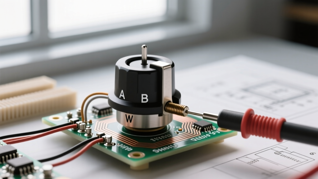
Trimpots, like the ubiquitous Bourns 3296 series, are designed for PCB mounting and 'set-and-forget' calibration. Because their orientation varies (top-adjust vs. side-adjust), you must rely on silkscreen markings on the resin body or the PCB footprint. The wiper is almost universally designated by a 'W' or the center pin in a linear 3-pin footprint. Always verify with a multimeter before applying power.
The Two Core Potentiometer Connections
There are exactly two ways to wire a potentiometer in a circuit: as a voltage divider (using all three pins) or as a rheostat (using two pins). Choosing the wrong configuration for your application will result in circuit failure.
Configuration A: The Voltage Divider (3-Pin Wiring)
This is the most common configuration, used primarily for generating a variable reference voltage or reading user input via a microcontroller's Analog-to-Digital Converter (ADC). According to SparkFun's voltage divider principles, the pot splits the input voltage proportionally based on the wiper's physical position.
Wiring Steps for Microcontroller ADC (e.g., Arduino A0):
- Connect Pin 3 to VCC (e.g., 5V or 3.3V).
- Connect Pin 1 to GND.
- Connect Pin 2 (Wiper) to the microcontroller's analog input pin.
As documented in the Arduino analog input guidelines, the high impedance of the ADC (typically >100 MΩ) ensures that negligible current is drawn from the wiper, preventing loading effects and ensuring accurate voltage sampling.
Configuration B: The Rheostat (2-Pin Variable Resistor)
When you need to vary current or resistance directly (e.g., dimming an LED or setting the gain on an op-amp), you wire the pot as a rheostat. This requires only two connections, but how you make those connections is a hallmark of professional engineering.
The 'Wiper-Tie' Rule: Never use Pin 1 and Pin 2 while leaving Pin 3 floating. If the wiper (Pin 2) loses physical contact with the resistive track due to dirt, vibration, or wear, the circuit becomes an open loop, causing erratic behavior or sudden voltage spikes. Always tie the unused outer lug to the wiper. For example, connect Pin 3 to Pin 2, and use Pin 1 and the tied Pin 2/3 node as your two circuit terminals. This ensures that if the wiper lifts, the circuit defaults to the maximum resistance of the track rather than an open circuit.
Decoding Tapers: Linear vs. Logarithmic
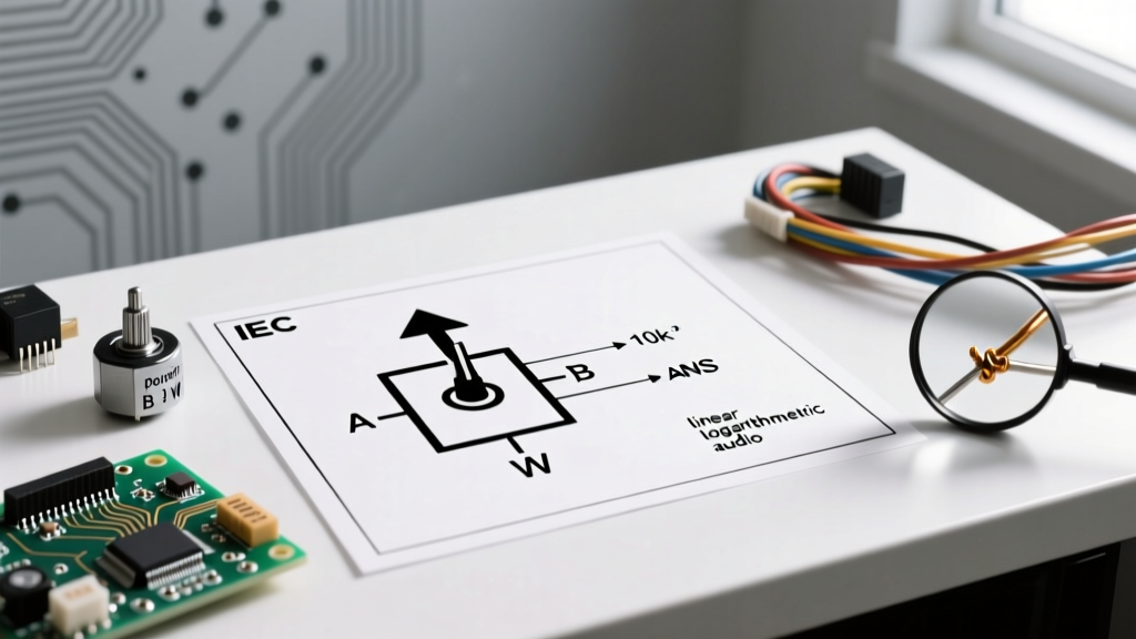
Identifying the taper (the mathematical relationship between shaft rotation and resistance change) is crucial. Using a linear pot for audio volume control will result in all perceived volume changes happening in the first 20% of the rotation.
| Marking Code | Taper Type | Resistance at 50% Rotation | Primary Application |
|---|---|---|---|
| B (e.g., B10K) | Linear | ~50% of total | Position sensors, ADC inputs, motor speed |
| A (e.g., A10K) | Logarithmic (Audio) | ~10% to 15% of total | Audio volume controls, VCA modulation |
| C (e.g., C10K) | Reverse Logarithmic | ~85% to 90% of total | Specialty audio fades, anti-log sensor scaling |
Multimeter Verification: Test Before You Solder
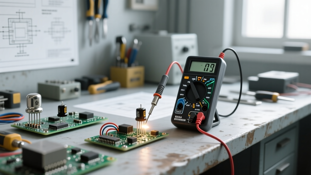
Because manufacturer markings can be cryptic (or rubbed off on salvaged parts), you must verify the taper and total resistance using a digital multimeter (DMM).
- Find Total Resistance: Set your DMM to the Ohms (Ω) setting. Place probes on Pin 1 and Pin 3. The reading should match the rated value (e.g., 10kΩ) within a ±20% tolerance.
- Verify the Wiper: Move one probe to Pin 2 (Wiper). Turn the shaft fully counter-clockwise. The resistance between Pin 1 and Pin 2 should read near 0Ω.
- Identify the Taper: Turn the shaft to the exact mechanical center (50% rotation). Measure the resistance between Pin 1 and Pin 2.
- If the reading is roughly half of the total resistance (e.g., ~5kΩ on a 10k pot), it is Linear (B).
- If the reading is significantly lower (e.g., ~1kΩ on a 10k pot), it is Logarithmic (A).
Critical Failure Modes and Power Limits
Engineering Warning: A standard 10kΩ carbon track potentiometer is typically rated for 0.5W of total power dissipation. However, the wiper element itself can usually only handle a fraction of that current. If you wire a 10k pot as a rheostat directly across a 12V supply to dim an LED, the initial current (I = V/R) might be low, but as you turn the knob toward 0Ω, the current spikes, instantly vaporizing the wiper contact. Always place a fixed series resistor in line with a rheostat to limit maximum current.
Ground Loops in Audio Wiring
When wiring audio potentiometers (A-taper) for guitar pedals or amplifiers, the metal casing of the pot must be grounded to act as a Faraday shield against 50/60Hz mains hum. However, do not use the Pin 1 ground lug to ground the casing if that lug is also carrying signal return current. This creates a ground loop, introducing audible hum. Instead, use a dedicated grounding lug (often found on the rear of the pot casing) or solder a separate wire directly to the metal chassis tab.
Summary Checklist for Prototyping
- ADC Interfacing: Use 3-pin voltage divider wiring. Ensure VCC matches the microcontroller's logic level (3.3V vs 5V) to prevent ADC clipping or damage.
- Current Limiting: Use 2-pin rheostat wiring, tie the unused lug to the wiper, and always use a series resistor to protect the wiper track.
- Taper Selection: Use 'B' (Linear) for microcontrollers and sensors; use 'A' (Log) for human audio perception.
- Mechanical Stress: When soldering panel-mount pots, use a heat sink clip on the lugs to prevent melting the internal plastic wiper carrier.
By treating potentiometer connections as a precise engineering discipline rather than an afterthought, you eliminate noise, prevent component destruction, and ensure your DIY electronics perform reliably in the real world.