
The NEC Framework for Bathroom Exhaust Fans
When electrical inspectors evaluate bathroom fan wiring, they are not just looking for a functional circuit; they are verifying strict adherence to the National Electrical Code (NEC). Bathroom environments present unique hazards due to the combination of high humidity, water sources, and electrical loads. A failed inspection not only delays project completion but can also leave homeowners vulnerable to fire and shock hazards. According to the NFPA 70 (National Electrical Code), bathroom ventilation must be meticulously planned, from the breaker panel to the switch box and the fan canopy itself.
This guide breaks down the exact code articles, common failure points, and technical specifications that inspectors use to grade bathroom exhaust fan installations during both rough-in and final inspections.
The 404.2(C) Neutral-at-the-Switch Mandate
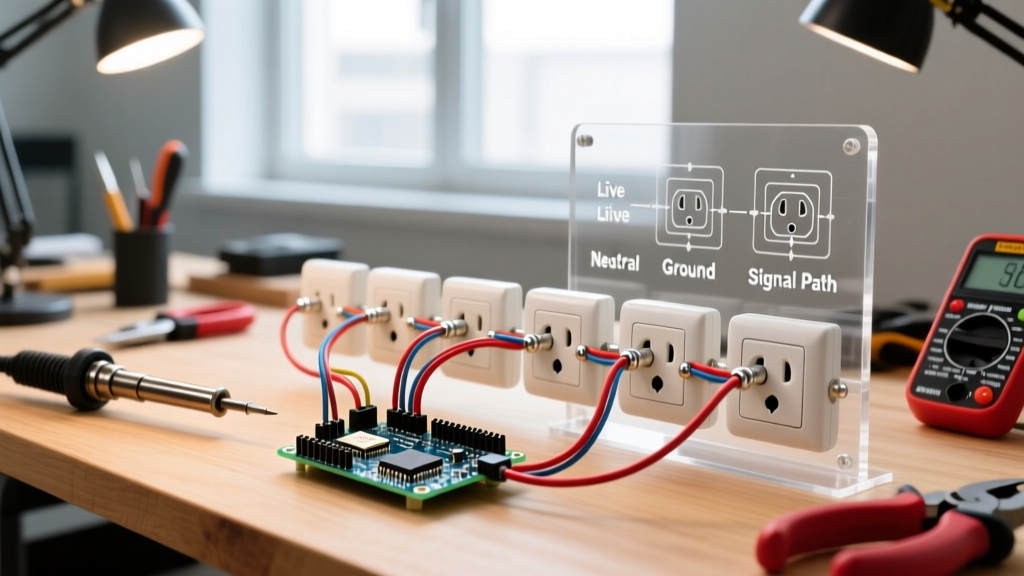
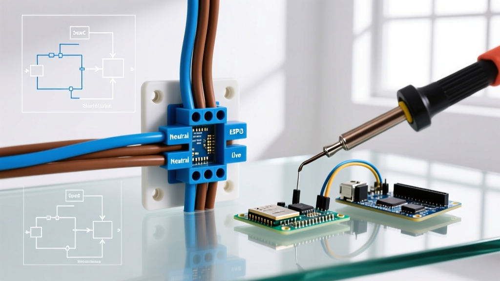
One of the most frequent reasons modern bathroom fan wiring fails inspection is the omission of a neutral wire at the switch box. Under NEC Article 404.2(C), switches controlling lighting and fan loads must be provided with a grounded (neutral) conductor. This is because modern exhaust fans frequently integrate humidity sensors, occupancy timers, or smart-home connectivity (such as the Leviton ODS10-IDW or Panasonic WhisperSense models). These electronic switches require a complete 120V circuit to power their internal logic boards, even when the fan is turned off. Inspectors will open the switch plate and immediately look for the white neutral wire capped in the back of the box. If you are pulling new 14/2 or 12/2 NM-B cable, you must use a 3-wire cable (14/3 or 12/3) or pull a separate neutral to comply with this mandate.
Dedicated Circuits vs. Shared Lighting Loops
Understanding NEC Article 210.11(C)(3) is critical for passing the rough-in inspection. The code requires at least one 20-ampere branch circuit to supply bathroom receptacle outlets. But where does the exhaust fan belong?
- Scenario A (Single Bathroom Served): If the 20A dedicated circuit supplies only that specific bathroom, the exhaust fan and lighting can be wired to this same 20A circuit. Inspectors will verify that no other bathrooms or non-bathroom loads are tapped into this loop.
- Scenario B (Multiple Bathrooms Served): If the 20A circuit supplies receptacles in multiple bathrooms, it cannot supply any other loads. In this case, your bathroom fan wiring must be routed to a separate 15A or 20A general lighting circuit.
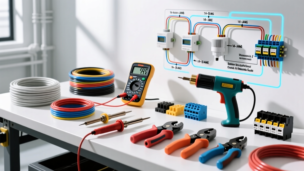
Inspector Tip: High-CFM commercial-grade fans or units with built-in resistive heaters (like the Panasonic WhisperWarm series) draw significant amperage. A 1500W heater element pulls roughly 12.5 Amps. If wired to a shared 15A lighting circuit, it will trip the breaker instantly. Inspectors will check the fan's UL nameplate amperage against the breaker size and wire gauge (12 AWG for 20A, 14 AWG for 15A) to ensure the circuit can handle the continuous load.
GFCI and AFCI Protection: Where Inspectors Look First
Ground-Fault Circuit Interrupter (GFCI) and Arc-Fault Circuit Interrupter (AFCI) protections are heavily scrutinized in wet areas. Under NEC 210.8(A), all 125-volt, single-phase, 15- and 20-ampere receptacles installed in bathrooms must have GFCI protection. But what about the fan itself?
The fan motor does not require GFCI protection unless it is installed in a specific zone or the manufacturer's installation instructions explicitly mandate it. Because NEC 110.3(B) requires installers to follow the manufacturer's listed instructions, if the fan manual specifies GFCI protection, the inspector will require it on the breaker or upstream receptacle.
The 'Over-Tub' Zone Restriction
If your bathroom fan wiring routes to a unit mounted directly over a bathtub or shower stall, NEC Article 410.4 and the fan's UL listing come into play. The fixture must be specifically marked by the manufacturer as 'Suitable for use over bathtubs and showers when connected to a GFCI-protected branch circuit.' If an inspector sees a standard dry-location fan mounted over a tub, or if it is over a tub but lacks GFCI protection at the breaker panel, it is an automatic red-tag failure. Furthermore, the fixture must be rated for damp or wet locations depending on whether it is subject to direct shower spray.
Box Fill and Canopy Wire Management
Bathroom fan housings often serve as their own junction boxes. Inspectors use NEC Article 314.16 to calculate box fill, ensuring the housing is not dangerously overstuffed with conductors, which can trap heat and damage wire insulation. When calculating box fill for the fan canopy, you must count:
- Each current-carrying conductor (hot and neutral) as one volume allowance.
- All grounding conductors combined as a single volume allowance.
- Cable clamps (if internal to the box) as a single volume allowance.
- Switch loops or timer modules as additional allowances.
| Conductor Size | Volume Allowance per Wire | Max Wires in Standard 18 cu in Fan Box |
|---|---|---|
| 14 AWG | 2.0 cubic inches | 9 total allowances |
| 12 AWG | 2.25 cubic inches | 8 total allowances |
If you are running a 12/3 cable to a fan with a heater and light, plus a 12/2 feed from the panel, you are dealing with multiple hots, neutrals, and grounds. Always verify the cubic-inch stamp on the interior of the fan's electrical knock-out box before terminating wires.
Common Wiring Violations Flagged During Rough-In
During the rough-in phase, before the drywall is laid, inspectors look at the physical security and routing of your NM-B (Romex) cable. According to Mike Holt Enterprises' NEC training guides, the following violations are the most commonly cited:
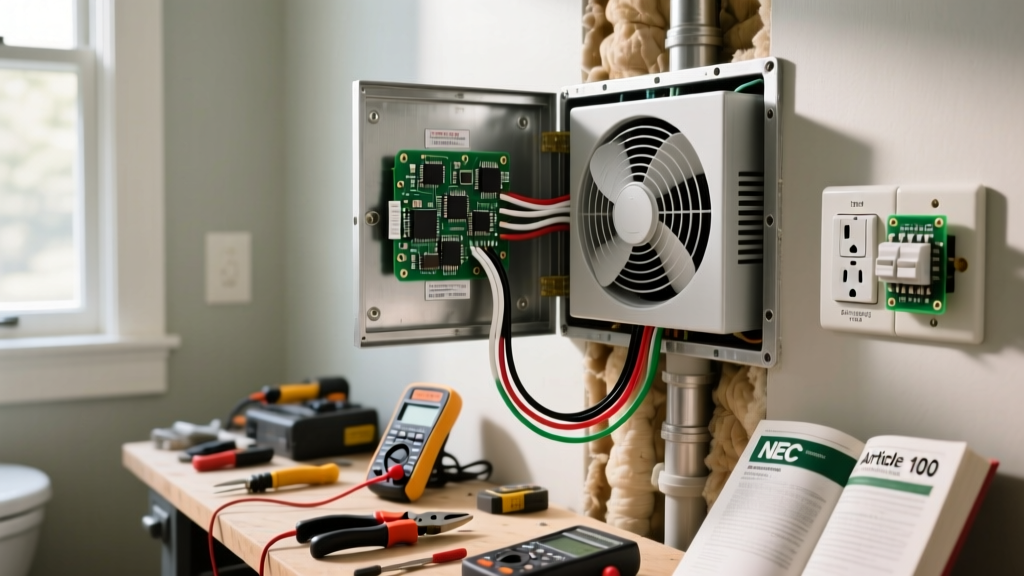
- Missing Cable Clamps: NM-B cable entering the metal fan housing must be secured by a listed ROMEX connector. Pushing the bare cable through a metal knockout will slice the PVC jacket and bare copper over time due to vibration from the fan motor.
- Improper Stapling Distances: NEC 334.30 requires NM-B cable to be stapled within 8 inches of the fan box (or 12 inches if using an oversized single-gang switch box without a clamp) and every 4.5 feet thereafter. Missing the 8-inch staple is an immediate fix-it ticket.
- Grounding Pigtails: Metal fan boxes must be grounded. Inspectors will tug on the bare copper ground wire to ensure the wire nut or WAGO connector is secure and that a proper pigtail runs to the green grounding screw on the fan housing.
- Exposed Sheathing Inside the Box: The outer PVC jacket of the NM-B cable must enter the box by at least 1/4 inch, but no more than that. Stripping back too much jacket leaves bare wires vulnerable to shorting against the metal housing; leaving too much jacket inside eats up valuable box fill volume.
Final Inspection Checklist for Electricians
Before calling for the final inspection, run through this compliance checklist to ensure your bathroom fan wiring meets all E-E-A-T standards and local amendments:
- Verify Breaker Sizing: Confirm 15A/14AWG or 20A/12AWG matching, especially for heater-integrated models.
- Test GFCI/AFCI: Use a receptacle tester or press the test button on the breaker to verify trip functionality if the fan is in the over-tub zone.
- Check Switch Neutrals: Ensure the white neutral is present and capped at the switch location for smart/timer switches.
- Inspect Ducting Grounding: While flexible metallic ducting is not a grounding path, ensure the fan housing itself is bonded to the equipment grounding conductor.
- Confirm UL Listings: Match the fan's installation manual (often required to be left inside the canopy or provided to the homeowner) with the physical installation location (damp vs. wet rated).
For further reading on ventilation specifications and amperage draws, consult the Panasonic Ventilation and Indoor Air Quality documentation. Mastering these code nuances ensures your bathroom fan wiring is safe, efficient, and guaranteed to pass inspection on the first visit.