
When a circuit fails, guessing is the most expensive troubleshooting method you can employ. Whether you are diagnosing a dead residential receptacle, tracking down a parasitic draw in an automotive ECU, or finding a short on a custom PCB, knowing how to use a multimeter effectively is the dividing line between an amateur and a master technician. This guide bypasses the basic "what is a dial" tutorials and dives straight into advanced diagnostic scenarios, common measurement traps, and the physics behind false readings.
The Diagnostic Mindset: Beyond Basic Voltage Checks
A multimeter is not just a display for numbers; it is a window into the electrical state of a system. According to All About Circuits, the most common mistake beginners make is treating the meter as a simple pass/fail indicator rather than a tool for mapping voltage gradients and resistance paths. Effective troubleshooting requires you to predict what the meter should read, compare it to what it does read, and deduce the physical fault from the delta.
Port Selection and the 10A Shunt Trap
Before touching a probe to a live circuit, you must understand the internal architecture of your meter's ports. A standard digital multimeter (DMM) like the Klein Tools MM400 or the industry-standard Fluke 117 features three primary ports:
- COM (Common): The ground reference. The black probe always lives here.
- VΩmA (Voltage, Ohms, Milliamps): Protected by an internal high-rupturing capacity (HRC) fuse, typically rated for 400mA to 500mA.
- 10A (Amperage): This port bypasses the fragile mA fuse and routes current through a heavy-duty internal metal shunt resistor.
The Fatal Error: If you leave your red probe in the 10A port and attempt to measure voltage across a wall outlet, you are effectively placing a dead short (the metal shunt) across 120V/240V AC. This will result in an arc flash, destroyed probes, and potentially severe injury. Always verify your probe placement matches your dial setting before making contact.
Troubleshooting Scenario A: Eliminating "Ghost Voltages"
You are troubleshooting a commercial lighting circuit. You measure 120V AC at a disconnected wire nut, but the light fixture won't turn on. Is the wire live?
This is a classic ghost voltage scenario. In long cable runs, unenergized wires running parallel to live wires act as a capacitor, picking up an induced AC voltage through capacitive coupling. A high-impedance digital multimeter (typically 10 Megohms input impedance) will read this phantom voltage as "real," leading to dangerous misdiagnoses.
The Solution: Low Impedance (LoZ) Mode
To solve this, you need a meter with a LoZ (Low Impedance) setting, such as the Fluke 117. When you switch to LoZ, the meter drops its internal input impedance to roughly 3 kilohms. This creates a small load that bleeds off the capacitively coupled ghost voltage, dropping the reading to 0V, while true hard-wired voltage sources will easily push through the 3kΩ load and still read 120V.
Troubleshooting Scenario B: Automotive Parasitic Draws
A customer complains their car battery dies after sitting for two days. You suspect a parasitic draw. Here is how to use a multimeter to track it down without blowing your meter's internal fuse.
- Preparation: Turn off the ignition, close all doors, and wait 15 minutes for the vehicle's CAN bus modules to enter sleep mode.
- Probe Placement: Move the red probe to the 10A port. Set the dial to DC Amps.
- Series Connection: Disconnect the negative battery terminal. Connect the black probe to the battery's negative post, and the red probe to the disconnected negative cable. The meter is now acting as a bridge, forcing all current to flow through the internal shunt.
- Reading: A normal sleep-state draw is typically between 30mA and 50mA (0.03A - 0.05A). If you read 1.2A, you have a massive drain.
- Isolation: Begin pulling fuses one by one. When you pull the fuse for the infotainment module and the amperage drops to 0.04A, you have isolated the faulty circuit.
Pro-Tip: The Voltage Drop Fuse Hack
Breaking the circuit to measure amperage is tedious. Instead, leave your meter on DC Millivolts (mV). Measure the voltage drop across the face of the fuses while the circuit is active. Using Ohm's Law and the known resistance of standard automotive blade fuses, a 1mV drop across a 10A MINI fuse roughly equates to 1 Amp of current flow. This allows you to scan an entire fuse box in seconds without pulling a single relay.
Troubleshooting Scenario C: The In-Circuit Resistance Illusion
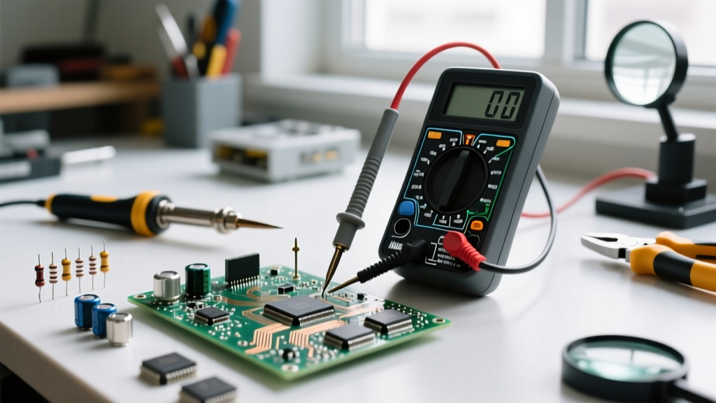
When testing resistors or checking for short circuits on a populated Printed Circuit Board (PCB), measuring resistance in-circuit is notoriously deceptive. A multimeter measures resistance by sending a tiny known current through the probes and measuring the resulting voltage drop.
If you place your probes across a 10kΩ resistor that is soldered into a board, you are not just measuring that resistor. You are measuring the parallel equivalent resistance of every other component, trace, and semiconductor junction connected to those same nodes. A 10kΩ resistor might read as 2.4kΩ simply because of a parallel microcontroller pin.
The Rule: Never trust an in-circuit resistance reading for a definitive component diagnosis. To accurately test a component, you must desolder at least one leg to isolate it from the parallel paths of the circuit.
Multimeter Safety Categories (CAT Ratings)
Using a CAT II meter on a CAT IV environment is a recipe for catastrophic failure. The Occupational Safety and Health Administration (OSHA) and the IEC 61010 standard define these categories based on the available fault current and transient voltage spikes in different electrical environments. Always match your meter's rating to the hazard.
| Category | Environment | Typical Application |
|---|---|---|
| CAT II | Local Level | Appliances, portable tools, standard household receptacles. |
| CAT III | Distribution Level | Hard-wired equipment, industrial control panels, distribution bus bars, lighting systems in commercial facilities. |
| CAT IV | Primary Supply Level | Utility meters, primary overcurrent protection, overhead service drops, pole transformers. |
As noted in the Fluke multimeter safety guidelines, a CAT III 1000V meter is actually safer than a CAT II 1000V meter because the CAT III rating implies a much higher internal arc-clearance and HRC fuse capability to withstand transient spikes from the utility grid.
Final Diagnostic Takeaways
Mastering how to use a multimeter requires an understanding of the physics occurring between your probes. By utilizing LoZ to defeat ghost voltages, leveraging voltage-drop measurements across fuses to save time, and respecting the parallel resistance paths of in-circuit testing, you elevate your troubleshooting from simple continuity checking to true electrical diagnostics. Always verify your meter's CAT rating, inspect your probe insulation for micro-tears, and never assume a circuit is dead until you have proven it on a known live source first.